
Technical Bulletin

Modbus TCP On-Board Communications
16 PowerXL DG1 Series VFD MN040010EN—May 2014 www.eaton.com
Modbus TCP On-Board Communications
Modbus/TCP Specifications
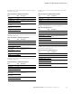
Table 32. Modbus/TCP Technical Data
Modbus/TCP Protocol
Modbus/TCP is a variant of the Modbus family. It is a
manufacturer-independent protocol for monitoring and
controlling automatic devices. Modbus/TCP is a client-server
protocol. The client makes queries to the server by sending
“request” messages to the server's TCP port 502. The
server answers client queries with “response” messages.
The term “client” can refer to a master device that runs
queries. Correspondingly, the term “server” refers to a slave
device that serves the master device by answering its
queries. Both the request and the response messages are
composed as follows.
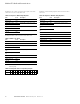
Byte 0. Transaction ID High
Byte 1. Transaction ID Low
Byte 2. Protocol ID High
Byte3. Protocol ID Low
Byte 4. Length field High
Byte 5. Length field Low
Byte 6. Unit identifier
Byte 7. Modbus function code
Byte 8. Data (of variable length)
Modbus/TCP vs. Modbus RTU
Compared to the Modbus RTU protocol, the Modbus/TCP
differs mostly in error checking and slave addresses. As the
TCP already includes an efficient error checking function, the
Modbus/TCP protocol does not include a separate CRC field.
In addition to the error checking functionality, the TCP is
responsible for resending packets and for splitting long
messages so that they fit the TCP frames. The slave address
field of the Modbus/RTU is named as the unit identifier field
in Modbus/TCP, and it is only used when one IP address
stands for several endpoints.
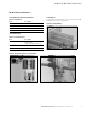
Hardware Specifications
Ethernet Port LED Indications
Ethernet LED
1. Ethernet Link Status
2. Ethernet Link Speed
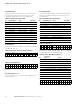
Table 33. Ethernet LED Description
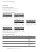
Ethernet LED Indications at Power Up
When PowerXL is powered up, an indicator test will be
performed. To allow a visual inspection, the following
sequence will be performed.
1. Turn first indicator Green, all other indicators off.
2. Leave first indicator on Green for approximately
0.25 second.
3. Turn first indicator on Red for approximately
0.25 second.
4. Turn first indicator on Green.
5. Turn second indicator (if present) on Green for
approximately 0.25 second.
6. Turn second indicator (if present) on Red for
approximately 0.25 second.
7. Turn second indicator (if present) Off.
If other indicators are present, test each indicator in
sequence as prescribed by the second indicator above.
If a Module Status indicator is present, it will be the first
indicator in the sequence, followed by any Network Status
indicators present. After completion of this power up test,
the indicator(s) will turn to a normal operational state.
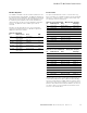
General Description Specification
Ethernet connections Interface RJ-45 connector
Communications Transfer cable Shielded twisted pair
Speed 10/100 Mb
Duplex Half/full
Default IP–address Mode DHCP with Auto-IP
Default static IP
configurations
Default static IP address 192.168.1.254
Default Network Mask 255.255.255.0
Default Gateway Address 192.168.1.1
LED Meaning
Ethernet link status Flashes with Ethernet message activity.
Ethernet link speed Displays the link speed.
Yellow LED on the Ethernet Jack is ON when link
speed is 100 mbps
Yellow LED on the Ethernet Jack is OFF when link
speed is 10 mbps