
Full Product Manual


Volume 2—Commercial Distribution CA08100003E—April 2016 www.eaton.com V2-T1-51
1
1
1
1
1
1
1
1
1
1
1
1
1
1
1
1
1
1
1
1
1
1
1
1
1
1
1
1
1
1
1.1
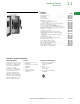
Switching Devices
Safety Switches
Technical Data and Specifications
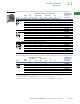
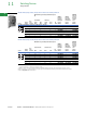
Typical Fusible, Double-Throw Schematic Diagram
Typical Non-Fusible, Double-Throw Schematic Diagram
Typical General-Duty, Double-Throw Schematic Diagrams
(with and without factory-installed neutral)
Short-Circuit Ratings Using Class “R”, “J” or “T” Fusing
Where Applicable
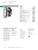
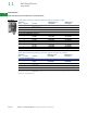
Dimensions
Approximate Dimensions in Inches (mm)
General-Duty, Non-Fusible, 240V, Two-Pole Solid Neutral,
Double-Throw, Compact Design
General-Duty, Non-Fusible, 240V, Two-Pole Solid Neutral,
Double-Throw, Quick-Make, Quick-Break Design
NEMA 3R, 30–400A, General-Duty, Non-Fusible,
Double-Throw
Notes
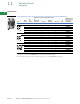
Class “H” fuse clips supplied as standard for 30–400A except Class “T” for 400A at 600V.
Rated at 10,000 rms symmetrical when using Class “H” fuses.
Table
is not applicable to the compact design shown on Page V2-T1-47. The compact design is
suitable for use on a circuit capable of delivering not more than 10,000 rms symmetrical amperes.
Class “R” fuse adapter kits are shown on Page V2-T1-14. Individual adapter kits are applicable as
shown on Page V2-T1-14 and yield the short-circuit ratings per the tables above when Class “R”
fuses are installed. When installed, Class “R” fuse adapter kits reject all fuses except Class “R.”
Class “J” fuse provisions can be obtained on most 60–400A safety switches by moving the fuse
base to a new position as instructed by the device publication label. Class “J” fuse adapter kits,
where needed, are shown on Page V2-T1-14 and yield the short-circuit ratings per the tables
above when Class “J” fuses are installed. Class “J” fuse provisions must be factory installed on
30A heavy-duty switches. Catalog numbers are shown in table on Page V2-T1-18. Class “J” fusing
is not applicable on 30–200A general-duty switches, 30–100A double-throw switches, and any
switch higher than 600A.
Class “T” fuse adapter kits are shown on Page V2-T1-14. Individual adapter kits are applicable
to 200–800A switches as shown on Page V2-T1-14 and yield the short-circuit ratings per the
tables to the left when Class “T” fuses are installed. On 1200A switches, Class “T” fuse provisions
can be obtained by moving the fuse base to a new position as instructed by the device publication
label.
Ampere
Rating
Voltage Ratings
Type 1 Type 3R Type 12 Type 4 and 4X
30 100k at 600 100k at 600 100k at 600 100k at 600
60 100k at 600 100k at 600 100k at 600 100k at 600
100 100k at 600 100k at 600 100k at 600 100k at 600
200 100k at 600 100k at 600 100k at 600 100k at 600
400 100k at 600 100k at 600 100k at 600 100k at 600
600 100k at 600 100k at 600 100k at 600 100k at 600
800 100k at 600 100k at 600 — —
1200 100k at 600 100k at 600 — —
Fusible Three-Pole
Two Sources
Fusible Three-
Pole Two Loads
ON
ON
OFF
ON
ON
OFF
ON
ON
OFF
ON
ON
OFF
S/N
Non-Fusible Three-
Pole Two Sources
or Two Loads
Non-Fusible Three-
Pole Two Sources
or Two Loads
Two Sources
ON
OFF
ON
ON
OFF
ON
S/N
Ampere
Rating Height (H) Width (W) Depth (D)
Depth (D2)
Weight
Lbs (kg)
NEMA 3R
30 14.69 (373.1) 9.63 (244.6) 10.81 (274.6) 5.23 (132.8) 12 (5.5)
60 14.69 (373.1) 9.63 (244.6) 10.81 (274.6) 5.23 (132.8) 12 (5.5)
100 14.69 (373.1) 9.63 (244.6) 10.81 (274.6) 5.23 (132.8) 12 (5.5)
Ampere
Rating Height (H) Width (W) Depth (D)
Depth (D2)
Weight
Lbs (kg)
NEMA 3R
30 24.63 (625.6) 11.94 (303.3) 9.88 (251.0) 5.38 (136.7) 34 (15.4)
60 24.63 (625.6) 11.94 (303.3) 9.88 (251.0) 5.38 (136.7) 34 (15.4
100 24.63 (625.6) 11.94 (303.3) 9.88 (251.0) 5.38 (136.7) 34 (15.4)
200 37.38 (949.5) 19.56 (496.8) 11.25 (285.8) 6.10 (154.9) 80 (36.3)
400 53.81 (1366.8) 23.13 (587.5) 12.50 (317.6) 8.88 (225.6) 140 (63.6)
W
C
L
H
D
D2