
Full Product Manual


Volume 2—Commercial Distribution CA08100003E—April 2016 www.eaton.com V2-T1-89
1
1
1
1
1
1
1
1
1
1
1
1
1
1
1
1
1
1
1
1
1
1
1
1
1
1
1
1
1
1
1.1
Switching Devices
Safety Switches
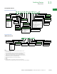
Catalog Number Selection
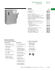
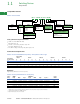
Pringle Bolted Pressure Switch
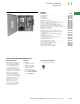
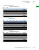
Pringle Mill Switch
2
(NEMA 1/3R/12 Enclosed)
Notes
1
Not UL listed. A separate control box may be required when adding accessories.
2
Does not carry UL listing.
3
Not an option with QA type switches. GF option includes control power transformer.
4
110 Vdc and 125 Vdc also available. Please contact the Cleveland, TN plant.
5
For different system voltage requirements, please contact the Cleveland, TN plant.
6
For QA switches, use 480V system catalog number when referencing a 208V system.
7
Only applicable if ordering a CPT only, without ground fault.
8
Only available with QA switches and in a top-feed configuration.
i
250 Vdc.
j
480 Vac.
k
Additional available accessories/options—door interlock, special nameplates,
custom dimensions, special paint and auxiliary contacts. Please inquire with the Cleveland, TN plant.
Switch
CB = CBC
QA = QA
FP = FP
EO = EO
1
Additional
Option
NF = Non-fused
8
Amperes
08 = 800A
12 = 1200A
16 = 1600A
20 = 2000A
25 = 2500A
30 = 3000A
40 = 4000A
50 = 5000A
2
60 = 6000A
2
Poles
2 = Two-pole
3 = Three-pole
4 = Four-pole
Wire
2 = Two-wire
3 = Three-wire
4 = Four-wire
Feed
B = Bottom
T = Top
Options
6 = With handle
suitable to meet
6’6” requirements
Auxiliary Contact
6 = 1NO/1NC
7 = 2NO/2NC
Interlock
K = Key interlock
provisions
System Voltage
5
208 = 208V
6
480 = 480V
600 = 600V
Blown Fuse Detector (BFD)
A = BFD with three normally ON
lights (does NOT trip)
AO = BFD with three normally OFF lights
(does NOT trip)
AX = BFD with NO lights (trips switch)
A9 = BFD with three normally ON
lights (trips switch)
AR = BFD with three normally OFF lights
(trips switch)
CB 08 3 3 B 120 480 K G R AO CT 5 NF
Voltage Control
3
120 = 120V
4
Control Power Transformer
3
CT = With control
power transformer
7
Phase Failure Relay
3
R = Single-phase voltage relay with
capacitor trip device (SPVR)
Ground Fault
3
G = Ground fault with
control power
transformer
GNX = Ground fault without
control power
transformer
Switch
PMS = Pringle Mill Switch
Option
k
W = With viewing window
Amperes
08 = 800A
12 = 1200A
16 = 1600A
20 = 2000A
25 = 2500A
30 = 3000A
40 = 4000A
Poles
2 = Two-pole
i
3 = Three-pole
j
Feed Exit
B = Bottom
T = Top
PMS 08 3 3 NF T B W
Feed Entry
B = Bottom
T = Top
Wire
2 = Two-wire
i
3 = Three-wire
j
Fusing
F = Fusible
NF = Non-fusible