
Datasheet


www.eaton.com/elx 11
Eaton is a registered trademark.
All other trademarks are property
of their respective owners.
Eaton’s Electrical Group
Electronics Division
114 Old State Road
Ellisville, MO 63021
United States
www.eaton.com/elx
© 2014 Eaton
All Rights Reserved
Publication No. 4315 — BU-SB14112
April 2014
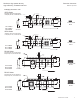
Temperature
t
t
P
t
s
T
C
-5°C
Time 25°C to Peak
Time
25°C
T
smin
T
smax
T
L
T
P
Preheat
A
Max. Ramp Up Rate = 3°C/s
Max. Ramp Down Rate = 6°C/s
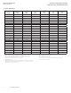
Table 1 - Standard SnPb Solder (T
c
)
Volume Volume
Packagemm
3
mm
3
Thickness <350 >
_
350
<2.5mm 235°C 220°C
>
_
2.5mm 220°C 220°C
Table 2 - Lead (Pb) Free Solder (T
c
)
Volume Volume Volume
Packagemm
3
mm
3
mm
3
Thickness <350 350 - 2000 >2000
<1.6mm 260°C 260°C 260°C
1.6 – 2.5mm 260°C 250°C 245°C
>2.5mm 250°C 245°C 245°C
Reference JDEC J-STD-020D
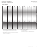
Profile Feature Standard SnPb Solder Lead (Pb) Free Solder
Preheat and Soak • Temperature min.(T
smin
) 100°C 150°C
• Temperature max. (T
smax
) 150°C 200°C
• Time (T
smin
to T
smax
) (t
s
) 60-120 Seconds 60-120 Seconds
Average ramp up rate T
smax
to T
p
3°C/ Second Max. 3°C/ Second Max.
Liquidous temperature (T
L
) 183°C 217°C
Time at liquidous (t
L
) 60-150 Seconds 60-150 Seconds
Peak package body temperature (T
P
)* Table 1Table 2
Time (t
p
)** within 5 °C of the specified classification temperature (T
c
) 20 Seconds** 30 Seconds**
Average ramp-down rate (T
p
to T
smax
) 6°C/ Second Max. 6°C/ Second Max.
Time 25°C to Peak Temperature 6 Minutes Max. 8 Minutes Max.
* Tolerance for peak profile temperature (T
p
) is defined as a supplier minimum and a user maximum.
** Tolerance for time at peak profile temperature (t
p
) is defined as a supplier minimum and a user maximum.
Solder reflow profile
North America
Eaton’s Electrical Group
Electronics Division
1225 Broken Sound Parkway NW
Suite F
Boca Raton, FL 33487-3533
Tel: 1-561-998-4100
Fax: 1-561-241-6640
Toll Free: 1-888-414-2645
Eaton’s Electrical Group
Electronics Division
P.O. Box 14460
St. Louis, MO 63178-4460
Tel: 1-636-394-2877
Fax: 1-636-527-1607
Europe
Eaton’s Electrical Group
Electronics Division
Burton-on-the-Wolds
Leicestershire, LE 12 5th UK
Phone: +44 (0) 1509 882 600
Fax: +44 (0) 1509 882 786
Eaton’s Electrical Group
Electronics Division
Avda Santa Eulalia, 290
Terrassa, Barcelona 08223 Spain
Phone: +34-93-736-2813
Fax: +34-93-783-5055
Asia Pacific
Eaton’s Electrical Group
Electronics Division
No.2, #06-01
Serangoon North Avenue 5
Singapore 554911
Tel: +65 6645 9888
Fax: +65 6728 3155
The only controlled copy of this Data Sheet is the electronic read-only version located on the Bussmann Network Drive. All other copies of this document are by definition uncontrolled. This bulletin is
intended to clearly present comprehensive product data and provide technical information that will help the end user with design applications. Bussmann reserves the right, without notice, to change
design or construction of any products and to discontinue or limit distribution of any products. Bussmann also reserves the right to change or update, without notice, any technical information contained
in this bulletin. Once a product has been selected, it should be tested by the user in all possible applications.
Life Support Policy: Bussmann does not authorize the use of any of its products for use in life support devices or systems without the express written approval of an officer of the Company. Life support
systems are devices which support or sustain life, and whose failure to perform, when properly used in accordance with instructions for use provided in the labeling, can be reasonably expected to result
in significant injury to the user.
DR Series High power density,
high efciency, shielded inductors
Technical Data 4315
Effective April 2014