
Cut Sheet


Effective February 2013
Supersedes December 2006
Technical Data TD04703002E
Cam selection for
pushbutton selectors
Introduction
Selector switches in their varied forms
(two-position, three-position, four-position, and
Roto-Push) are a big factor contributing to the
great flexibility of control that a well-rounded line
of “pushbuttons” can achieve.
But because selector switches can be made
to perform in such complex and varied ways,
selection and application can be difficult. This is
only because a well thought-out approach is not
readily apparent.
This document provides a time-proven systematic
approach that will work in all cases.
Many complex selector switch control schemes
have been solved using the methods outlined
here. Even if you work with it only occasionally,
we ensure that you will be able to easily work
out the most complex schemes.
Cam and contact block selection is better
understood if you:
•
Work with each incoming and outgoing wire
(each circuit) separately
•
Recognize that the terms NO and NC only
identify the type of contact by its mode before
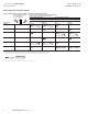
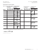
mounting it to the operator. The “X-O” chart
shows how that contact will act after assembly
to the operator with the selected cam shape
•
Each cam has two separate lobes, each of
which operates one of the two plungers on
the contact block independently of each other.
Those are identified as position A (top) and
position B (bottom). The position designations
give direction in selecting and mounting the
contact blocks
Contents
Description Page
Cam selection ............................2
Summary ................................3
Roto-Push. ...............................4
Contact block selection. ....................5
Three-position selector switch. ...............6
Four-position selector switch. ................7
Three-position Roto-Push switch. .............8
Glossary of terms. ........................10