
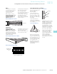
Cut Sheet

Volume 8—Sensing Solutions CA08100010E—November 2012 www.eaton.com V8-T12-35
12
12
12
12
12
12
12
12
12
12
12
12
12
12
12
12
12
12
12
12
12
12
12
12
12
12
12
12
12
12
12.1
Sensor Learning Course
Learning Module 23: Limit Switches, Proximity Sensors and Photoelectric Sensors
Output Configurations
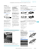
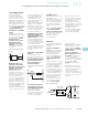
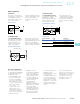
Single Output
As in other control devices,
several output configurations
are available for sensors.
Fixed single outputs, either
1NO or 1NC, are very
common and NO is the most
common. Fixed single output
sensors cannot change
configuration to the other
circuit.
Single Output
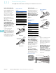
Programmable Output
A programmable output
sensor has one output, NO or
NC, depending on how the
output is wired when it’s
installed. Sometimes the
output configuration is
selected using a switch. On
photoelectric sensors this is
called a light/dark switch. This
allows you to program the
sensors output normally open
(NO) or normally closed (NC).
Programmable Output
Accessory Considerations
The choice of control circuit,
of using single, programmable
or complementary outputs
are dependent upon:
●
Voltage available—Does
the control circuit have
provisions for supplying
DC? Some control circuits
have interfacing circuitry
for DC sensors even if the
main control voltage
source is AC
●
Control circuit current
requirements—If the
circuit requires a current
greater than the rating on
the sensor, an interposing
relay can be used
●
Application output
requirements—While NO
is the most commonly
used, certain applications
may require the circuit
logic provided by NC, or
even the complementary
configured sensors
●
Switching speed
requirements—For
applications requiring high
speed, such as counting,
DC sensors may be
required. AC circuits are
limited by operations per
second (because of the
AC sine wave), and are
typically slower than DC
Load
Brown
Blue
L1
L2
Load
No Wiring Option
12
34
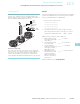
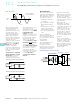
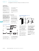
Complementary Output
A complementary output
sensor has two outputs, 1NO
and 1NC Both outputs
change state simultaneously
when the target enters or
leaves the sensing field.
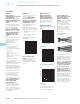
The output logic for the
normally open and normally
closed contact configurations
for an inductive proximity
sensor is shown in the table
below.
Complementary Output
Output Logic
●
Connected logic device—
Probably the most
important factor for sensor
circuit and output
configuration is the device
to which the sensor is to
be connected. What type
of input the PLC, counter,
relay, and so on, can accept
is the determining factor
for which sensor output is
chosen
Other considerations are
whether the sensor will need
LED indication of its status
and whether there is short
circuit protection, reverse
polarity protection or wire
termination needed
Output Configuration Target Output State
NO Absent Non-conducting (OFF)
Present Conducting (ON)
NC Absent Conducting (ON)
Present Non-conducting (OFF)
Load
1
3
4
+
–
2
Load
N.C.
N.O.