
Cut Sheet


Volume 8—Sensing Solutions CA08100010E—July 2015 www.eaton.com V8-T3-57
3
3
3
3
3
3
3
3
3
3
3
3
3
3
3
3
3
3
3
3
3
3
3
3
3
3
3
3
3
3
3.7
Inductive Proximity Sensors
Ferrous Only Tubular Sensors
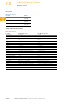
Technical Data and Specifications
Ferrous Only Tubular Sensors
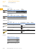
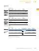
Wiring Diagrams
Pin numbers are for reference, rely on pin location when wiring.
Ferrous Only Tubular Sensors
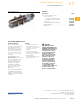
Dimensions
Approximate Dimensions in Inches (mm)
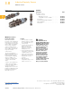
Ferrous Only Tubular Sensors
Connector Models
Description Two-Wire AC/DC Sensors Three-Wire DC Sensors
Operating voltage 20–250 Vac/dc 10–30 Vdc
Maximum load current 100 mA 100 mA
Switching frequency 15 Hz 1000 Hz
Leakage current 2.5 mA maximum <0.01 mA
Voltage drop 10 V maximum 1.5 V maximum
Holding current 5 mA minimum —
Burden current — 17 mA
Protection Transient, power on false pulse suppression Short-circuit protection
Switching hysteresis <15% rated sensing distance <15% rated sensing distance
Repeat accuracy <1% sensing distance <1% sensing distance
Time delay before availability <10 ms <10 ms
Output indicator LED Lights when output is ON Lights when output is ON
Operating temperature –13 to 131 °F (–25 to 55 °C) –13 to 131 °F (–25 to 55 °C)
Enclosure ratings NEMA 4, 4X, 6, 6P, 12 and 13 (IP67) NEMA 4, 4X, 6, 6P, 12 and 13 (IP67)
Shock 30 g sine wave, 11 ms per IEC68-2-76 30 g sine wave, 11 ms per IEC68-2-76
Vibration 10 to 55 Hz, 1 mm amplitude in all three planes 10 to 55 Hz, 1 mm amplitude in all three planes
Housing material Stainless steel Stainless steel
Operating Voltage
Connector Models (Face View Male Shown)
Output Micro Mini
Two-Wire Sensors
20–250 Vac/dc
50/60 Hz
NO
Three-Wire Sensors
10–30 Vdc NO
(PNP)
—
Catalog Number A B C D
Two-Wire Models
E57FAL18A2SA M18 x 1 3.11 (79) 1.38 (35) 1.73 (44)
E57FAL18A2B1 M18 x 1 3.90 (99) 1.34 (34) 2.56 (65)
Three-Wire Models
E57FAL18T111SD M18 x 1 3.11 (79) 1.14 (29) 1.97 (50)
L2
L1
Load
L1
L2
Load
(–)
+V
Load
“A”
LED
“B”
“C
”
“D”