
Cut Sheet


V8-T3-100 Volume 8—Sensing Solutions CA08100010E—July 2015 www.eaton.com
3
3
3
3
3
3
3
3
3
3
3
3
3
3
3
3
3
3
3
3
3
3
3
3
3
3
3
3
3
3
3.17
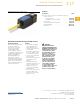
Inductive Proximity Sensors
E51 Limit Switch Style, Factory Sealed 6P+ Sensors
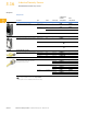
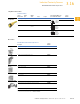
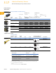
Wiring Diagrams
Pin numbers are for reference, rely on pin location when wiring.
E51 Limit Switch Style, Factory Sealed 6P+
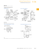
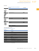
Dimensions
Approximate Dimensions in mm [in]
E51 Limit Switch Style, Factory Sealed 6P+
Note
1
Can accommodate both U.S., 29.4 [1.16] x 59.5 [2.34] and DIN, 30 [1.18] x 60 [2.36],
mounting dimensions.
Operating
Voltage Output
Mini-Connector Models
Cable Models (Face View Male Shown)
Two-Wire Sensors
20–264 Vac or
Vdc 50/60 Hz
NO or NC (NO shown)
Four-Wire Sensors
120 Vac
50/60 Hz
NO and NC
10–30 Vdc NO and NC NPN
NO and NC PNP
21
43
L2
or (–)
L1
or +V
Load
Black
White
Green
L1 or
(–)
L2
or +V
Load
21
43
L2
L1
Load
Load
Black
White
Orange
Red
Green
Load
Load
N.C.
N.O.
L2
L1
21
43
(–)
+V
Load
Load
Black
White
Orange
Red
Green
(–)
+V
Load
Load
N.O.
N.C.
21
43
(–)
+V
Load
Load
Black
White
Orange
Red
Green
(–)
+V
Load
Load
N.C.
N.O.
16.3
[0.64]
10.2
[0.4]
79.5
[3.13]
11. 4
[0.45]
39.0
[1.54]
6.20
[0.24]
5.20
[0.204]
25.0
[0.99]
35.1
[1.38]
38.4
[1.51]
20.1
[0.79]
125.9
[4.96]
28.7
[1.13]
40.1
[1.58]
[10–32] Tap 9.65 [0.38] Deep
Two Holes for Rear Mtg.
C
L
C
L
Cable Pig Tail or
Mini Pin Connector
Factory Assembled
1
1