
Cut Sheet


Volume 8—Sensing Solutions CA08100010E—November 2012 www.eaton.com V8-T12-19
12
12
12
12
12
12
12
12
12
12
12
12
12
12
12
12
12
12
12
12
12
12
12
12
12
12
12
12
12
12
12.1
Sensor Learning Course
Learning Module 23: Limit Switches, Proximity Sensors and Photoelectric Sensors
Coil/Core Size
An important factor in the
range of the sensor is the
construction of the coil/core.
An open coil with no core will
produce a field that could be
actuated by a target from any
direction. That wouldn’t be
very practical for industrial
applications.
For an inductive proximity
sensor, the sensor coil that
generates the field fits inside
of a ferrite core. This cup-
shaped piece of ferrite
material is called a cup core.
This core directs the field and
shapes it.
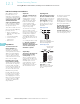
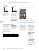
Coil/Core Construction
A protective cap prevents
dust or other environmental
hazards from entering the
sensor.
Shielding
To focus the intensity of the
field, the coil can be
shielded. In a standard range
sensor, the ferrite cup core
shapes the field to emanate
straight from the sensing
face of the sensor. In a
sense, shielding it.
An extended range coil/core
assembly does not use the
standard cup core, just a core
of ferrite. This unshielded
device allows the extension
of the sensing range. There is
less ferrite to absorb the
electromagnetic field, so its
range is wider and a little
longer.
The decision to use a non-
shielded sensor will impact
the mounting of the sensor,
as we will discuss that next.
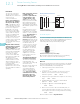
Shielding
Cap Coil Cup
Core
Sensor
Head
Non-shielded
Shielded
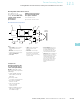
Mounting Considerations
A shielded sensor can be fully
embedded in a metal
mounting block without
affecting the range. It is
sometimes referred to as a
flush mount sensor.
A non-shielded sensor needs
clearance around it (called the
metal-free zone) which is
determined by its sensing
range. Otherwise, the sensor
will sense the metal
mounting and be
continuously operating.
The design of a sensor can
affect how it is mounted.
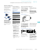
Clear Zone
Mounting two sensors
closely together can also be
a problem. If you position
two proximity sensors too
close together—either side
by side or facing each other
head to head—the two fields
will clash with one another.
Each sensor needs to be
mounted at least three
times its own sensing
range away from the other.
The use of an alternative
frequency head on one of the
sensors will prevent adjacent
sensors’ sensing fields from
interacting.
In the Workplace
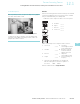
At an auto manufacturing plant, a drilling operation is performed
on the valve blocks to allow for mounting the cover plates. The
operation is totally unmanned.
An Inductive Proximity Sensor Monitors Drilling Operation
The drill bit must form holes in an extremely hard material.
Breaking drill bits is a fairly common occurrence. For this
reason, a proximity sensor is in place. If a break occurs, the
sensor signals the system to stop the operation so the drill
bit may be replaced.