
Cut Sheet


V8-T3-4 Volume 8—Sensing Solutions CA08100010E—July 2015 www.eaton.com
3
3
3
3
3
3
3
3
3
3
3
3
3
3
3
3
3
3
3
3
3
3
3
3
3
3
3
3
3
3
3.0
Inductive Proximity Sensors
Introduction
Technical Reference
Inductive Proximity Sensors
General
There are a number of factors which should be considered when applying induction proximity
sensors. A detailed discussion of these factors can be found on Page V8-T12-4. Presented below
are a few of the more important considerations for quick reference.
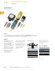
Mounting
Inductive proximity sensors
are available in two
classifications: shielded (also
known as embeddable or
flush mountable) and
unshielded (non-embeddable
or non-flush mountable).
What these terms refer to is
the distance to surrounding
metal that the device can be
mounted. In the case of a
shielded sensor the device
can be mounted with the
sensor completely
surrounded by metal.
In the case of an unshielded
sensor, a metal free zone
must be provided when
mounting the sensor. The
size of the metal free zone is
dependent on both the size of
the sensor and the type of
sensing range it has, for
example, standard or
extended.
Mounting Ranges
Where a and b are the metal
free dimensions.
When mounting the sensors,
do not exceed the following
recommended torque
specifications.
Torque Specifications
Shielding a b
Standard Range
Shielded 0 0
Unshielded 2 x Sn Cap height
Extended Range
Semi-shielded Sn d
Non-embeddable 2 x Sn Cap height
a
b
d
Stainless Steel
Nickel-Plated
Brass
12 mm Diameter
35 lb-in (4.0 Nm) 20 lb-in (2.3 Nm)
18 mm Diameter
70 lb-in (7.9 Nm) 70 lb-in (7.9 Nm)
30 mm Diameter
70 lb-in (7.9 Nm) 70 lb-in (7.9 Nm)