
Cut Sheet

Volume 10—Enclosed Control CA08100012E—June 2015 www.eaton.com V10-T15-25
15
15
15
15
15
15
15
15
15
15
15
15
15
15
15
15
15
15
15
15
15
15
15
15
15
15
15
15
15
15
15.1
Accessories and Modification Codes
Accessories
Auxiliary Contacts, continued
Notes
1
Front- (top) mount tall version is for use with Frame B electrical wire bridges and link kits and toolless plug combination connection kits: XTCEXRLB, XTCEXSDLB, XTPAXTPCB, XTPAXTPCRB, XTPAX.
2
Can be mounted to the left side of contactor only. Cannot be used in combination with front- (top) mount auxiliary contacts or mechanical interlocks.
3
One early-make contact (1NO
E
), one late-break contact (1NC
L
).
Interlocked opposing contacts, to IEC/EN 60947-5-1 Annex L (positively driven), within the auxiliary contact modules (not NO [early make] and NC [late break] contacts) and for the built-in auxiliary
contacts of the XTCE007B_–XTCE032C_.
Auxiliary break contact can be used as mirror contact to IEC/EN 60947-4-1 Annex F (not NC [late break] contact).
No auxiliary contacts can be fitted between two contactors.
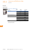
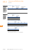
Conventional
Thermal Current,
Open at 60°C
I
th
= I
e
,
AC-1 in Amps Poles
Contact
Configuration Circuit Symbol
Pkg.
Qty.
Screw Terminals
Catalog Number
Spring Cage Terminals
Catalog Number
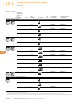
Frame B–C—Front- (Top) Mount—Tall Version, continued
1
16 4 2NO-2NC 5 XTCEXFATC22 —
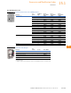
Frame C—Side-Mount
10 2 1NO-1NC 1 XTCEXSCC11
2
—
Frame D–G
16 2 2NO 5 XTCEXFBG20 —
16 2 1NO-1NC 5 XTCEXFAG11 —
16 2 1NO-1NC 5 XTCEXFBG11 —
16 2 2NC 5 XTCEXFBG02 —
16 4 4NO-0NC 5 XTCEXFBG40 XTCEXFBGC40
16 4 3NO-1NC 5 XTCEXFBG31 XTCEXFBGC31
16 4 2NO-2NC 5 XTCEXFBG22 XTCEXFBGC22
16 4 2NO-2NC 5 XTCEXFAG22 XTCEXFAGC22
16 4 1NO-3NC 5 XTCEXFBG13 XTCEXFBGC13
16 4 0NO-4NC 5 XTCEXFBG04 XTCEXFBGC04
16 4 1NO
E
-1NC
L
5 XTCEXFBLG22
3
XTCEXFBLGC22
3
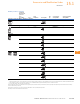
54
53
61
62
71
72
83
84
54
53
61
62
14 24
13 23
54
53
61
62
14
13
21
22
12
11
21
22
14
13
23
24
33
34
43
4
4
14
13
21
22
33
34
43
44
14
13
21
22
31
32
43
4
4
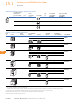
54
53
61
62
71
72
8
3
84
14
13
21
22
31
32
41
42
12
11
21
22
31
32
41
42
14
13
21
22
35
36
47
48