
Cut Sheet


V10-T2-50 Volume 10—Enclosed Control CA08100012E—June 2015 www.eaton.com
2
2
2
2
2
2
2
2
2
2
2
2
2
2
2
2
2
2
2
2
2
2
2
2
2
2
2
2
2
2
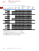
2.1
NEMA Contactors and Starters
Freedom Full Voltage Controls
Wiring Diagrams
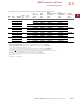
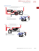
Non-Reversing Starter—Single- and Three-Phase Non-Combination
Non-Reversing Starter—Combination
Three-Wire Control
”A“
Stop
Stop Stop
Start
Start Start
2/13
1
3/14
2/13
1
3/14
Remote Pilot Devices
3/14
Not for Use with Auto
Reset OL Relays
1
Two-Wire Control
When More than One
Pushbutton Station is
Used, Omit Connector
”A“ and Connect per
Sketch Below
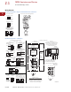
Connections for Non-Reversing Starter
Figure 2
Fusible Control Transformer
Field Conversion to Single-Phase
Figure 1
Front View Diagram
Connections for Starters
Connections for Control Stations
M
M
Add Dotted
Connection
OL
M
L3
L2
L1
OL
Motor
260878 D4
A1
A2
96
95
OL
Reset
2/13
3/14
T1
2
4
T2
6
T3
6/
T1
2/
T2 T3
4/
95
Reset
96
97
98
1
A1
A2
135
T1
T2
T3
“C”
T3
T1
4/
T2
L1
1
A1 A2
L2
3
T2
6/
L3
5
2/
T1
Motor
T1
T2
Separate Control
Remove Wire “C” if Supplied and
Connect Separate Control Lines to
the Number 1 Terminal on the Remote
Pilot Device and to the Number 96
Terminal on the Overload Relay
Omit Connector
Stop
Start
Remote
21
2/13
43
Local
1
3/14
Stop (OFF)
Start (ON)
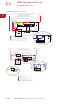
Combined Remote and Local for Figures 1 and 2
Remote Control
Local Control
“A”
When More than One
Pushbutton Station is Used,
Omit Connector “A” and
Connect per Sketch Below
Stop
Start
Start
Stop
Start
3/14
2/13
1
2/13
1
3/14
Two-Wire
Control
Not for
Use with
Auto Reset
OL Relays
Three-Wire
Control
1
3/14
Black/ White
Black/ White
Connect to Coil Terminals
”A1“ and ”A2“
3
4
4
3
X1
X2
12
Stop (OFF)
43
Start (ON)
3/14
2/13
1
Black
Red
Red
2 4
3
1
Hand
Auto
1
3/14
YellowYellow
Black
Red
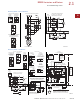
Figure D
Two-Position Selector Switch
Figure A
START/STOP Pushbuttons
Figure B
START/STOP Selector Switch
Figure C
Three-Position Selector Switch
Hand
3/14
Yellow
Auto
1
Black
Remote
Switch
Red
2
1
4
3
Start (ON)
3/14
1
Black
Red
Figure E
Pilot Light (Motor RUN)
Connect to ”A1“
and ”A2“ Terminals
To Coil
Terminal
”A1“
Figure F
START/STOP with Pilot Light
3
4
1
3/14
2/13
2
1
Stop (OFF)
Start (ON)
Black/ White
Black/ White
X1
X2
Local
Control
(Flange
mounting
if used)
See
Figures
A, B, C, D,
E and F
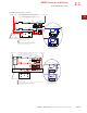
CPT
Fusible Control Transformer
(If used)
See Figure 2
Omit this
Connector
if Figure 2
is Used
Disconnecting
Means
D.S. or C.B.
L1 L2 L3
Fuse
Fuse
Fuse
3
Secondary
Connections
G
1
H3
1
X2
H2
4
H4
XF
1
H1
X1
CPT
Primary
Connections
Connections for Dual
Voltage Rated Transformer—
See Transformer Nameplate
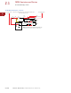
Remove Wire “C” (Figure 1) if Used
and Connect as Shown Below
(All other starter wires remain
as shown in Figure 1)
5
L2L1 L3