
Cut Sheet

V10-T2-84 Volume 10—Enclosed Control CA08100012E—June 2015 www.eaton.com
2
2
2
2
2
2
2
2
2
2
2
2
2
2
2
2
2
2
2
2
2
2
2
2
2
2
2
2
2
2
2.3
NEMA Contactors and Starters
Freedom Multispeed Starters
Wiring Diagrams
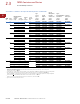
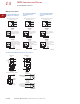
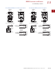
Multispeed
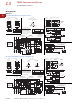
Two-Speed One-Winding Constant Horsepower
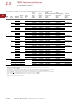
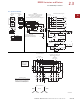
Two-Speed One-Winding Constant or Variable Torque
260819 D3
Starter Elementary Diagram
Lines
Slow
Slow
Slow
Stop
Figure C
Figure B
Fast
Fast
Fast
Figure 1
Motor Connections
Constant Horsepower Motor
Remove Wire “C” if Supplied
and Connect as Shown Below
(All other wiring remains
as shown in Figure 1)
Control Circuit Transformer (If used)
A1 A2
L2
2OL
G
X2 X1XF
1
Fuse
Fuse
Fuse
H1
F
L1
13
H4
CPT
Reset
95
96
L3
5
H31H24
Connections for Dual Voltage Rated
Transformer—See Transformer Nameplate
Primary
Connections
Secondary
Connections
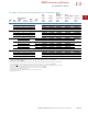
Figure 2
Front View of Panel
Contactors
“F” and “1S”
Are Mechanically
Interlocked
AC Lines
Wire “F”—
Used with Local
Control Pushbuttons
Omit This
Connection if
Figure 2 is Used
“C”
Speed
Slow
Fast
Connect Lines
L1
To Motor Terminals
L2 L3
Together
T6
T1
T4
T2
T5
T3
T4, T5, T6
Remote Control Stations
Figure B
3
Slow
4
Stop
1
2
3
4
6
2
5
1
OFF
X = Contact Closed
Contact
A
B
Position
Fast
OFF
X
X
Slow
Slow
A
B
Fast Fast
Fast
Slow
3
5
6
1
3
Figure C
5
2
Remove Wire “C” When it is
Supplied. Connect Separate
Control Lines to the Number 1
Terminal on the Remote Control
Station and the Number 96
Terminal on Overload Relay 2OL.
Separate Control
CPT
Fusible Control
Transformer
(If used)
See Figure 2
1OL 2OL
1
2
4
Fast
OFF
Slow
5
2S
F1S
A1
F
A2
95 96 95 96
1S
6
2
F
2S
1
L1
3
5
4
A1
A2
Reset
97
96
98
95
T2
T1
T1
2/
4/
T2
T3
T3
6/
1OL
5
L3L1
1
1
L2
3
2S
A1
A2
A2
F
A1
5
4
3
2
2OL
T3T2T1
95
6/
2/ 4/
Reset
97
96
98
6
3
F
1S
A2
A1
2S
F
1S
A1
1S
A2
A1
1S
2S
A2
6
95 96 95 96
A1
F
A2
1OL 2OL
L2
1
A1
A2
4
5
2
3
1
S
1OL
2S
F
2OL
2S
1OL
F
2OL
2S
1OL
F
2OL
L1 L2 L3
Constant
Horsepower
Motor
T4
T4
T1
T3
T5
T3
T5
T2
T6
T1
T2
T6
1S
1S
2S
2S
TB
T6 T5
T4
6
4 5
260818 D3
Starter Elementary DiagramFigure 1
Motor Connections
1OL 2OL
1
2
4
OFF
Slow
5
S
2F S
A2
1F
A1
95 96 95 96
S
2F
6
2
2F
S
Figure C
Figure B
Stop
1
L1
3
Slow
Fast
Fast
5
4
A1
A2
Reset
97
96
98
95
T4
T6
T1
2/
4/
T2
T5
T3
6/
2OL
5
L3L1
1
L2
3
2F
A1
A2
A2
S
A1
3
2
5
4
1OL
T3T2T1
95
6/
2/ 4/
Reset
97
96
98
6
3
1F
1F
A2
A1
2F
Fast
Slow
Fast
Slow
1F
S
A1
2F
S
A2
A1
1F
2F
A2
6
95 96 95 96
A2
1F
A1
1OL 2OL
L2
Constant
Torque
Variable
Torque
T4
T1
T3
T5
T2
T6
T5
T3
T1
T2
T6
T4
1OL
S
2F
2OL
S
1OL
2F
2OL
S
1OL
2F
2OL
1F
1F
Motor
L1 L2 L3
AC Lines
AC Lines
A1
A2
2
3
4
5
1
1
1F
Speed
Slow
Fast
Connect Lines
L1
To Motor Terminals
L2 L3
Together
T6
T1
T4
T2
T5
T3
T1, T2, T3
TB
T1 T3
T2
1
2 3
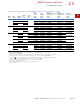
Remote Control Stations
Figure B
3
Slow
4
Stop
1
2
3
4
6
2
5
1
OFF
X = Contact Closed
Contact
A
B
Position
Fast
OFF
X
X
Slow
Slow
A
B
Fast Fast
Fast
Slow
3
5
6
1
3
Figure C
5
2
Variable
Torque
T5
T5 T6
T3
T3
T1
T1
T2
T6
T4
T4
T2
Constant
Torque
Remove Wire “C” if Supplied
and Connect as Shown Below
(All other wiring remains
as shown in Figure 1)
Control Circuit Transformer (If used)
A1 A2
L2
2OL
G
X2 X1XF
1
Fuse
Fuse
Fuse
H1
S
L1
13
H4
CPT
Reset
95
96
L3
5
H31H24
Connections for Dual Voltage Rated
Transformer—See Transformer Nameplate
Primary
Connections
Secondary
Connections
Figure 2
Remove Wire “C” when it is
Supplied. Connect Separate
Control Lines to the Number 1
Terminal on the Remote Control
Station and the Number 96
Terminal on Overload Relay 2OL.
Separate Control
Front View of Panel
Contactors
“1F” and “S”
are Mechanically
Interlocked
Wire “F”—
Used with Local
Control Pushbuttons
Omit This
Connection if
Figure 2 is Used
“C”
CPT
Fusible Control
Transformer
(If used)
See Figure 2