Electrical Sector Solutions Volume 10: Enclosed Control
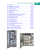
Volume 10—Enclosed Control Tab 1—Overview . . . . . . . . . . . . . . . . . . . . . . . . . . . . . . . . . . . . . . . . . . V10-T1-1 Tab 2—NEMA Contactors and Starters . . . . . . . . . . . . . . . . . . . . . . . . V10-T2-1 Tab 3—IEC Contactors and Starters . . . . . . . . . . . . . . . . . . . . . . . . . . V10-T3-1 Tab 4—Lighting Contactors . . . . . . . . . . . . . . . . . . . . . . . . . . . . . . . . . V10-T4-1 Tab 5—Reduced Voltage Starters . . . . . . . . . . . . . . . . . . . . . . . . .
Copyright Dimensions, Weights and Ratings Dimensions, weights and ratings given in this catalog are approximate and should not be used for construction purposes. Drawings containing exact dimensions are available upon request. All listed product specifications and ratings are subject to change without notice. Photographs are representative of production units. Terms and Conditions All prices and discounts are subject to change without notice.
Introduction Eaton is a global leader in power distribution, power quality, control and automation, and monitoring products. At Eaton, we believe a reliable, efficient and safe power system is the foundation of every successful enterprise. Through innovative technologies, cutting-edge products and our highly skilled services team, we empower businesses around the world to achieve a powerful advantage.
Introduction Icons Green Leaf Eaton Green Solutions are products, systems or solutions that represent Eaton benchmarks for environmental performance. The green leaf symbol is our promise that the solution has been reviewed and documented as offering exceptional, industry-leading environmental benefits to customers, consumers and our communities.
Overview Enclosed Control 1.1 Enclosed Control Products Welcome . . . . . . . . . . . . . . . . . . . . . . . . . . . . . . . . . . . . . . . . . . . . . . . Eaton Corporation . . . . . . . . . . . . . . . . . . . . . . . . . . . . . . . . . . . . . . . . Eaton Support and Service Center Capabilities . . . . . . . . . . . . . . . . . . Technical Reference Enclosure Types . . . . . . . . . . . . . . . . . . . . . . . . . . . . . . . . . . . . . . . Enclosure Ratings . . . . . . . . . . . . . . . . . . . .
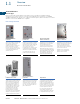
1.1 1 Overview Enclosed Control Products Contents Enclosed Control Products Description 1 Enclosed Control Products Technical Reference . . . . . . . . . . . . . . . . . . . . . Enclosure Types . . . . . . . . . . . . . . . . . . . . . Enclosure Ratings . . . . . . . . . . . . . . . . . . . . Motor Circuit Elements . . . . . . . . . . . . . . . . Power Supplies . . . . . . . . . . . . . . . . . . . . . . Functions of Control . . . . . . . . . . . . . . . . . . Two- and Three-Wire Control . . . . . . .
1.
1.1 Overview Enclosed Control Products 1 Technical Reference 1 1 Enclosures provide mechanical and electrical protection for operator and equipment. Brief descriptions of the various types of enclosures offered by Eaton are given below. See NEMA® Standards Publication No. 250 for more comprehensive descriptions, definitions and/or test criteria. All Eaton enclosures are NEMA ICS 6 compliant.
1.1 Overview Enclosed Control Products Enclosure Ratings 1 IEC IP Index of Protection Ratings 1 First Number Description Second Number 0 Description No protection 0 No protection 1 Protection against solid objects greater than 50 mm 1 Protection against vertically falling drops of water 2 Protection against solid objects greater than 12 mm 2 Protection against dripping water when tilted up to 15 degrees 3 Protection against solid objects greater than 2.
1.1 1 1 1 1 1 1 Overview Enclosed Control Products IEC Environmental Enclosure Ratings—Examples of Designations IP 4 4 IP Characteristic letters first characteristic numeral (See previous page) Characteristic letters first characteristic numeral (See previous page) Second characteristic numeral (See previous page) Second characteristic numeral (See previous page) An enclosure with this designation is protected against the penetration of solid objects greater than 1.
Overview Enclosed Control Products 1.1 Power Supplies 1 All electrical power supplied as AC or DC—primarily AC—generation, transmission and some distribution of power at high voltage—most power distribution at use voltage for industrial and residential is 600V and under—AC power generally at a frequency of 60 Hz—50 and 25 Hz used in some specific areas—AC distribution at use location single- or three-phase—limited areas have two-phase.
1.1 1 1 1 1 Enclosed Control Products Two- and Three-Wire Control Two-Wire Control Three-Wire Control Two-Wire Wiring L2 1 PD 3 L1 OL 1 1 1 1 1 M 1 1 1 1 M Three-wire control is a control function that uses a momentary contact pilot device and a holding circuit contact to provide low voltage protection (LVP). Line Diagram—connection representation but not wiring configuration—sequence and function of devices but not location—symbols do not represent physical construction of device.
NEMA Contactors and Starters Freedom Breaker Combination— Bi-Metallic OL 2.1 Freedom Full Voltage Controls Product Description . . . . . . . . . . . . . . . . . . . . . . . . . . . . . . . . . . . . . . . Features . . . . . . . . . . . . . . . . . . . . . . . . . . . . . . . . . . . . . . . . . . . . . . . . Standards and Certifications . . . . . . . . . . . . . . . . . . . . . . . . . . . . . . . . Additional Reference . . . . . . . . . . . . . . . . . . . . . . . . . . . . . . . . . . . . . .
2.1 2 NEMA Contactors and Starters Freedom Full Voltage Controls Contents Freedom Full Voltage Controls Description 2 Page Freedom Full Voltage Controls Catalog Number Selection . . . . . . . . . . . . . . . . Cover Control . . . . . . . . . . . . . . . . . . . . . . . . . . Contactors Non-Reversing Contactors . . . . . . . . . . . . . Reversing Contactors . . . . . . . . . . . . . . . . . Starters Non-Combination Starters . . . . . . . . . . . . . Combination Starters—Fusible and Non-Fusible . . . .
NEMA Contactors and Starters Freedom Full Voltage Control ISO 9001 Certification When you turn to Eaton’s products, you turn to quality. The International Standards Organization (ISO®) has established a series of standards acknowledged by 91 industrialized nations to bring harmony to the international quest for quality. The ISO certification process covers 20 quality system elements in design, production and installation that must conform to achieve registration.
2.
NEMA Contactors and Starters Freedom Full Voltage Controls 2.
2.
NEMA Contactors and Starters Freedom Full Voltage Controls 2.
2.
NEMA Contactors and Starters Freedom Full Voltage Controls 2.1 Type 1 Non-Combination Empty Enclosure (Box 1 Only) 2 There is a universal empty enclosure for the non-metallic Type 1 Non-Combination Box 1 regardless of the starter or the contactor needed. The only difference is the length of the easily interchangeable reset rod. The reset rod kit provides everything needed to install the correct reset rod, including all the reset rod lengths, a protective shroud, a paddle and a reset button with nut.
2.
NEMA Contactors and Starters Freedom Full Voltage Controls 2.
2.
NEMA Contactors and Starters Freedom Full Voltage Controls 2.
2.
NEMA Contactors and Starters Freedom Full Voltage Controls 2.
2.
NEMA Contactors and Starters Freedom Full Voltage Controls 2.
2.
NEMA Contactors and Starters Freedom Full Voltage Controls 2.
2.
NEMA Contactors and Starters Freedom Full Voltage Controls 2.
2.
NEMA Contactors and Starters Freedom Full Voltage Controls 2.
2.
NEMA Contactors and Starters Freedom Full Voltage Controls 2.
2.
NEMA Contactors and Starters Freedom Full Voltage Controls 2.
2.
NEMA Contactors and Starters Freedom Full Voltage Controls 2.
2.
NEMA Contactors and Starters Freedom Full Voltage Controls 2.
2.
NEMA Contactors and Starters Freedom Full Voltage Controls 2.
2.
NEMA Contactors and Starters Freedom Full Voltage Controls 2.
2.
NEMA Contactors and Starters Freedom Full Voltage Controls 2.
2.
NEMA Contactors and Starters Freedom Full Voltage Controls 2.
2.
NEMA Contactors and Starters Freedom Full Voltage Controls 2.
2.
NEMA Contactors and Starters Freedom Full Voltage Controls 2.
2.
NEMA Contactors and Starters Freedom Full Voltage Controls 2.
2.
NEMA Contactors and Starters Freedom Full Voltage Controls 2.
2.
2.
2.
2.1 NEMA Contactors and Starters Freedom Full Voltage Controls Reversing Starter—Non-Combination Connections for Reversing Starter Remote Control Stations Hold Down Pushbutton S.P.D.T. Switch Forward 1 5 F 3 1 Reverse OL 2 R 5 Reverse 2 Contactors “F” and “R” are Mechanically Interlocked Lines L1 L2 L3 Forward 3 2 Starter Elementary Diagram F Pushbutton 2 T1 T2 OL R T3 F 3 2 4 Rev.
2.1 2 Freedom Full Voltage Controls Non-Reversing Cover Control Type 1 C400GK Control Options 2 2 NEMA Contactors and Starters Local Control Options (If used) Refer to Diagram Inside Enclosure for Connections Figure A START/STOP Pushbutton Figure D Pilot Light (Motor RUN) S.P.S.T.
NEMA Contactors and Starters Freedom Full Voltage Controls 2.1 C600M Wiring Kit Diagrams 1/L1 OR SEPARATE CONTROL 2 STOP/START OR OFF/ON OVAL.
2.
NEMA Contactors and Starters Freedom Full Voltage Controls 2.
2.1 2 2 NEMA Contactors and Starters Freedom Full Voltage Controls C600M Wiring Kit Diagrams, continued 1/L1 OR SEPARATE CONTROL RED 2 LIGHTING 2 CONTACTOR/COIL REF.
2.1 NEMA Contactors and Starters Freedom Full Voltage Controls Reversing Cover Control Type 1 C400GR Control Options Local Control Options (If used) Refer to Diagram Inside Enclosure for Connections Figure A Pushbutton FORWARD/ STOP/ REVERSE Figure B Pilot Light (FORWARD) Add Connector “F” Between Aux.
2.2 2 NEMA Contactors and Starters A200 Full Voltage Controls Contents A200 Full Voltage Controls Description 2 Page A200 Full Voltage Controls Catalog Number Selection . . . . . . . . . . . . . . . . Product Selection Combination Non-Reversing Starters— Circuit Breaker. . . . . . . . . . . . . . . . . . . . . . Combination Non-Reversing Starters— Circuit Breaker with CPT . . . . . . . . . . . . . .
2.
2.
NEMA Contactors and Starters A200 Full Voltage Controls 2.
2.
NEMA Contactors and Starters A200 Full Voltage Controls 2.
2.3 2 NEMA Contactors and Starters Freedom Multispeed Starters Contents Freedom Multispeed Starters Description 2 Freedom Multispeed Starters Catalog Number Selection . . . . . . . . . . . . . . . . Cover Control . . . . . . . . . . . . . . . . . . . . . . . . . . Non-Combination Starters . . . . . . . . . . . . . . . . Combination Starters . . . . . . . . . . . . . . . . . . . . Wiring Diagrams . . . . . . . . . . . . . . . . . . . . . . .
2.
2.3 NEMA Contactors and Starters Freedom Multispeed Starters 2 Cover Control Flange Control Kits Factory Installed 2 For on-the-job conversion of Type 1, 3R, 4X and 12 enclosed starters. Knockouts are provided on the Type 1 flange. Type 3R, 4X and 12 have prepunched holes with removable hole plugs. To order factory installed pilot devices, change the ninth character of the catalog number to the alpha shown in the table below.
NEMA Contactors and Starters Freedom Multispeed Starters 2.
2.
2.
2.
NEMA Contactors and Starters Freedom Multispeed Starters 2.
2.
NEMA Contactors and Starters Freedom Multispeed Starters 2.
2.
NEMA Contactors and Starters Freedom Multispeed Starters 2.
2.
NEMA Contactors and Starters Freedom Multispeed Starters 2.
2.
NEMA Contactors and Starters Freedom Multispeed Starters 2.
2.
NEMA Contactors and Starters Freedom Multispeed Starters 2.
2.
2.
2.3 2 2 Multispeed Two-Speed One-Winding Constant Horsepower Figure 1 Motor Connections Remote Control Stations Figure B Fast Figure C Fast 4 T4 3 2 5 5 B 2 A B X = Contact Closed 2 F 2OL 1S T4 T3 2S 1OL 1S F 2OL F 2 Figure B Connect Lines Remove Wire “C” When it is Speed Supplied.
2.
2.
2.
IEC Contactors and Starters ECX Enclosed Control 3.1 XT IEC Power Control Non-Metallic Enclosure—Contactors and Starters Product Description . . . . . . . . . . . . . . . . . . . . . . . . . . . . . . . . . . . . Features and Benefits . . . . . . . . . . . . . . . . . . . . . . . . . . . . . . . . . . . Standards and Certifications . . . . . . . . . . . . . . . . . . . . . . . . . . . . . . Catalog Number Selection . . . . . . . . . . . . . . . . . . . . . . . . . . . . . . . Cover Control Options . . . .
3.1 3 IEC Contactors and Starters XT IEC Power Control Contents IEC Non-Metallic Enclosure—Contactors and Starters Description 3 Page Non-Metallic Enclosure—Contactors and Starters Catalog Number Selection . . . . . . . . . . . . . . . . Cover Control Options . . . . . . . . . . . . . . . . . . . Product Selection . . . . . . . . . . . . . . . . . . . . . . . Metallic Enclosure—Contactors and Starters . . . . Combination Motor Controllers . . . . . . . . . . . . . . .
3.1 IEC Contactors and Starters XT IEC Power Control Catalog Number Selection 3 XT IEC Line Non-Metallic Enclosed Control 3 EC X 09 E 5 A A A - 00 3 Design X = XT IEC Class 09 = Non-combination non-reversing starter Overload Range See table below Page V10-T3-4 0.1–0.16 A A 0.16–0.24 B 0.24–0.4 C A= B= C= D= E= FLA Ratings Size F–H 18–32 A 4–6 I I B 6–10 J C 9–12 K FLA Ratings 0.33–1.
3.1 3 3 IEC Contactors and Starters XT IEC Power Control Product Selection CI-K Basic Enclosures CI-K Basic Enclosures 12 Dimensions in Inches (mm) 3 3 Width Height External Depth 3.94 (100.0) 6.30 (160.0) 3.94 (100.0) 3 5.71 (145.0) 3 4.72 (120.0) 7.87 (200.0) 4.92 (125.0) 3 6.30 (160.0) 3 6.30 (160.0) 3 7.87 (200.0) 9.45 (240.0) 6.30 (160.0) 11.02 (280.0) 6.30 (160.0) 3 Internal Depth Internal Mounting Type Pkg. Qty. 2.87 (73.0) With mounting rail 1 3.11 (79.
IEC Contactors and Starters XT IEC Power Control 3.
3.
IEC Contactors and Starters XT IEC Power Control 3.
3.1 3 IEC Contactors and Starters XT IEC Power Control Contents IEC Metallic Enclosure—Contactors and Starters Description 3 Page Non-Metallic Enclosure—Contactors and Starters . . Metallic Enclosure—Contactors and Starters Catalog Number Selection . . . . . . . . . . . . . . . . Product Selection Non-Combination Starters . . . . . . . . . . . . . Combination Starters . . . . . . . . . . . . . . . . . Wiring Diagrams . . . . . . . . . . . . . . . . . . . . . . . Combination Motor Controllers . . . .
3.
3.
IEC Contactors and Starters XT IEC Power Control 3.
3.
IEC Contactors and Starters XT IEC Power Control 3.1 Type 1 Non-Combination Empty Enclosure (Box 1 Only) 3 There is a universal empty enclosure for the non-metallic Type 1 Non-Combination Box 1 regardless of the starter or the contactor needed. The only difference is the length of the easily interchangeable reset rod. The reset rod kit provides everything needed to install the correct reset rod, including all the reset rod lengths, a protective shroud, a paddle and a reset button with nut.
3.
IEC Contactors and Starters XT IEC Power Control 3.
3.
IEC Contactors and Starters XT IEC Power Control 3.
3.
IEC Contactors and Starters XT IEC Power Control 3.
3.
IEC Contactors and Starters XT IEC Power Control 3.
3.
IEC Contactors and Starters XT IEC Power Control 3.
3.
IEC Contactors and Starters XT IEC Power Control 3.
3.
IEC Contactors and Starters XT IEC Power Control 3.
3.
IEC Contactors and Starters XT IEC Power Control 3.
3.
IEC Contactors and Starters XT IEC Power Control 3.
3.
IEC Contactors and Starters XT IEC Power Control 3.
3.
3.
3.
3.1 IEC Contactors and Starters XT IEC Power Control Non-Combination Starters (Reversing) SPDT Switch For 3 Reversing Starter Elementary Diagram Connections for Reversing Starter Remote Control Stations Lines L1 L2 L3 Hold Down Pushbutton For 3 Rev 1 3 1 5 F 3 F T1 OL T2 T3 R Pushbutton OL F For 3 3 AC Motor 3 R 3 2 4 Rev 3 OL R 5 Rev 3 Contactors “F” and “R” are Mechanically Interlocked “C” Stop 5 1 Stop For. Rev.
3.
IEC Contactors and Starters XT IEC Power Control 3.
3.
3.1 IEC Contactors and Starters XT IEC Power Control Reversing Cover Control 3 Type 1 C600M Control Options (To be used with Box 1 Only) 3 Schematic Symbol Legend 3 Normally Open Auxiliary 3 Normally Closed Auxiliary Normally Open Momentary PB 3 Normally Closed Momentary PB Contactor Coil 3 Red Pilot Light 3 Green Pilot Light 3 Normally Closed Overload Auxiliary 3 Normally Open Overload Auxiliary 3 M22-XLED230-T: Used to lower voltage for pilot lights.
3.
IEC Contactors and Starters XT IEC Power Control 3.1 Contents Enclosed XT Combination Motor Controller Description Page Non-Metallic Enclosure—Contactors and Starters . . . Metallic Enclosure—Contactors and Starters . . . . Combination Motor Controllers Catalog Number Selection . . . . . . . . . . . . . . . . Cover Control . . . . . . . . . . . . . . . . . . . . . . . . . . Product Selection Non-Reversing Starters . . . . . . . . . . . . . . . . Non-Reversing Starters with CPT . . . . . . . .
3.
3.
3.
IEC Contactors and Starters XT IEC Power Control 3.
Lighting Contactors Electrically Held Lighting Contactors Mechanically Held Lighting Contactor 4.1 UL Rated AC Contactors Product Description . . . . . . . . . . . . . . . . . . . . . . . . . . . . . . . . . . . . . . . Application Description . . . . . . . . . . . . . . . . . . . . . . . . . . . . . . . . . . . . Standards and Certifications . . . . . . . . . . . . . . . . . . . . . . . . . . . . . . . . Additional Reference . . . . . . . . . . . . . . . . . . . . . . . . . . . . . . . . . . . . . .
4.1 4 Lighting Contactors UL Rated AC Contactors Contents UL Rated AC Contactors Description 4 UL Rated AC Contactors Catalog Number Selection . . . . . . . . . . . . . . . . Enclosures . . . . . . . . . . . . . . . . . . . . . . . . . . . . Cover Control . . . . . . . . . . . . . . . . . . . . . . . . . . Product Selection . . . . . . . . . . . . . . . . . . . . Operation Non-Combination Contactors. . . . . . . . . . . . Combination Contactors . . . . . . . . . . . . . . . Accessories . . . . . . . .
4.
4.
4.
4.
4.1 Lighting Contactors UL Rated AC Contactors Class ECL03—Non-Combination Electrically Held Lighting Contactor No.
4.1 4 4 4 4 Lighting Contactors UL Rated AC Contactors Class ECL03—Non-Combination Electrically Held Lighting Contactor, continued No.
4.1 Lighting Contactors UL Rated AC Contactors Operation A permanent magnet is built into the contactor structure that will maintain the contactor in its energized state indefinitely without using control power. When energized, a DC current is applied to the latch coil, producing a magnetic field that reinforces the polarity of the permanent magnet, pulling in the contactor. The current to the coil is disconnected by the coil clearing interlock.
4.1 4 4 4 4 Lighting Contactors UL Rated AC Contactors Class ECL04—Non-Combination Magnetically Latched Lighting Contactor, continued No.
4.1 Lighting Contactors UL Rated AC Contactors Combination Contactors 4 Class ECL12 and ECL13—Combination Lighting Contactor—Fusible Disconnect Max. Amp Rating 1 No.
4.1 4 4 4 4 Lighting Contactors UL Rated AC Contactors Class ECL14 and ECL15—Combination Lighting Contactor—Thermal Magnetic Circuit Breaker Max. Amp Rating 1 Continuous Ampere Rating at 40°C No.
Lighting Contactors UL Rated AC Contactors 4.1 Accessories Auxiliary Contacts Power Poles for C30CN C30CN Electrically Held Contactors—The base C30CN product line can accept up to four auxiliary contacts (2NO/2NC), which are mounted on the top of the unit. The auxiliary contacts, rated A600, are also suitable for use on low-level circuits down to 12 V, 5 mA. The C30CN can be configured with up to 12 poles (30 A maximum per pole).
4.
Lighting Contactors UL Rated AC Contactors 4.
4.
4.1 Lighting Contactors UL Rated AC Contactors Magnetically Latched Combination Contactors L2 L3 H4 3 XF H3 Local Control (Flange mounting if used) + 3 H2 ”C“ Red NC X1 NO – 2 M Black ON 4 4 X2 G Connections for Dual Voltage Rated Transformer—See Transformer Nameplate 1 L1 3 L2 4 5 L3 – M L2 Control Module Fusible Control Transformer Figure 2 OFF 4 L1 D.S. or C.B.
4.1 4 Lighting Contactors UL Rated AC Contactors Electrically Held Non-Combination Contactors—CN35 with C600 Control 4 4 4 4 4 4 4 4 4 4 4 4 4 4 4 4 4 4 4 4 4 4 4 4 4 4 4 4 4 V10-T4-18 Volume 10—Enclosed Control CA08100012E—June 2015 www.eaton.
4.1 Lighting Contactors UL Rated AC Contactors Electrically Held Non-Combination Contactors—CN35 with C600 Control 1/L1 OR SEPARATE CONTROL STOP/START OR OFF/ON OVAL.
4.
Reduced Voltage Starters Enclosed S611 with Breaker Disconnect 5.1 Product Description . . . . . . . . . . . . . . . . . . . . . . . . . . . . . . . . . . . . . . . Features and Benefits . . . . . . . . . . . . . . . . . . . . . . . . . . . . . . . . . . . . . Options . . . . . . . . . . . . . . . . . . . . . . . . . . . . . . . . . . . . . . . . . . . . . . . . Communications . . . . . . . . . . . . . . . . . . . . . . . . . . . . . . . . . . . . . . . . . Standards and Certifications . . . . . . . . . .
5.1 5 Reduced Voltage Starter S611 Solid-State Soft Stater Contents S611 Solid-State Soft Stater Description 5 Page S611 Solid-State Soft Stater Options . . . . . . . . . . . . . . . . . . . . . . . . . . . . . . Communications . . . . . . . . . . . . . . . . . . . . . . . Standards and Certifications . . . . . . . . . . . . . . Additional Reference . . . . . . . . . . . . . . . . . . . . Catalog Number Selection . . . . . . . . . . . . . . . . Product Selection Non-Combination . . . . . . . . . . .
Reduced Voltage Starter S611 Solid-State Soft Stater User Interface Module (UI) The S611 has an easy to use User Interface Module (UI) that allows the user to configure the device and to read system parameters and values. The UI includes an LED display and keypad to scroll through the various parameters. The UI allows the user to modify control parameters, enable or disable protections, set communication variables, monitor system values such as line voltages and currents and access the fault queue.
5.
Reduced Voltage Starter S611 Solid-State Soft Stater 5.
5.
Reduced Voltage Starter S611 Solid-State Soft Stater 5.
5.
Reduced Voltage Starter S611 Solid-State Soft Stater 5.
5.
Reduced Voltage Starter S611 Solid-State Soft Stater 5.
5.
Reduced Voltage Starter S611 Solid-State Soft Stater 5.1 Wiring Diagram 5 Sample—S611 with CPT and HOA Selector Switch 5 S611 STARTER Ø1 Ø1 L1 Ø2 Ø2 L2 Ø3 Ø3 L3 5 C L1/1 DISCONNECT T1 C L2/3 5 T2 MOTOR 5 T3 C L3/5 5 L1 REMOTE 5 L2 FUSE (2) 5 L11 FUSE 1 L12 X1 5 X2 X2 GND.
5.1 5 5 Reduced Voltage Starter S611 Solid-State Soft Stater Dimensions See Tab 14 for box dimensions for Type 1, 3R, 4X and 12. Minimum Enclosure Box Numbers Combination with Circuit Breaker Non-Combination Combination with Disconnect Switch Rating SSRV Box No. 1 Box No. 1 Box No.
Reduced Voltage Starter S801+/S811+ IT. Solid-State Soft Starters 5.2 Contents Reduced Voltage Starter Description Page Reduced Voltage Starter Options . . . . . . . . . . . . . . . . . . . . . . . . . . . . . . . Standards and Certifications . . . . . . . . . . . . . . Additional Reference . . . . . . . . . . . . . . . . . . . . Catalog Number Selection . . . . . . . . . . . . . . . . Cover Control . . . . . . . . . . . . . . . . . . . . . . . . . . Product Selection Non-Combination . . . . . . . . .
5.2 5 5 5 5 5 5 5 5 5 5 5 5 5 Reduced Voltage Starter S801+/S811+ IT. Solid-State Soft Starters Digital Interface Module The S811+ has an easy to use Digital Interface Module (DIM) that allows the user to configure the device and to read system parameters. The DIM includes an LCD display and keypad to scroll through the various menus.
Reduced Voltage Starter S801+/S811+ IT. Solid-State Soft Starters 5.2 Catalog Number Selection 5 IT.
5.2 Reduced Voltage Starter S801+/S811+ IT. Solid-State Soft Starters 5 Cover Control 5 For on-the-job conversion of Type 1, 3R, 4, 4X and 12 enclosed starters. Knockouts are provided on the Type 1 flange. Type 3R, 4, 4X and 12 have prepunched holes with removable hole plugs. 5 5 5 Flange Control Kits 5 Factory Installed Pilot Devices To order factory installed pilot devices, change the ninth character of the catalog number to the alpha shown in the table below.
Reduced Voltage Starter S801+/S811+ IT. Solid-State Soft Starters 5.
5.2 5 Reduced Voltage Starter S801+/S811+ IT.
Reduced Voltage Starter S801+/S811+ IT. Solid-State Soft Starters Class ECS93—Non-Combination Reduced Voltage Soft Starter—S811+ Amps 5.
5.2 5 Reduced Voltage Starter S801+/S811+ IT.
Reduced Voltage Starter S801+/S811+ IT. Solid-State Soft Starters 5.
5.2 5 5 5 Reduced Voltage Starter S801+/S811+ IT.
Reduced Voltage Starter S801+/S811+ IT. Solid-State Soft Starters 5.
5.2 5 Reduced Voltage Starter S801+/S811+ IT.
Reduced Voltage Starter S801+/S811+ IT. Solid-State Soft Starters 5.
5.2 5 5 Reduced Voltage Starter S801+/S811+ IT.
Reduced Voltage Starter S801+/S811+ IT. Solid-State Soft Starters 5.
5.2 5 5 Reduced Voltage Starter S801+/S811+ IT.
Reduced Voltage Starter S801+/S811+ IT. Solid-State Soft Starters 5.2 Wiring Diagrams 5 S801+/S811+ 01 02 03 L1 L2 L3 L1 L2 L3 5 T1 T2 Motor T3 T1 T2 T3 5 5 IT.
5.2 5 5 5 Reduced Voltage Starter S801+/S811+ IT. Solid-State Soft Starters S801+/S811+ with CPT and Power Supply IT.
Reduced Voltage Starter S801+/S811+ IT. Solid-State Soft Starters 5.2 Dimensions 5 See Tab 14 for box dimensions for Type 1, 3R, 4X and 12. See Tab 9 for box dimensions for Type 7/9. 5 Minimum Enclosure Box Numbers Non-Combination Combination with Fuses Combination with HMCP Rating SSRV Box No. 1 Box No. 1 Box No.
5.3 Reduced Voltage Starter Freedom Three-Phase Magnetic Starters 5 Contents 5 Freedom Three-Phase Magnetic Starters Catalog Number Selection . . . . . . . . . . . . . . . . Cover Control . . . . . . . . . . . . . . . . . . . . . . . . . . Product Selection Autotransformer . . . . . . . . . . . . . . . . . . . . . Part Winding . . . . . . . . . . . . . . . . . . . . . . . . Wye Delta . . . . . . . . . . . . . . . . . . . . . . . . . . Part Winding Pump Control . . . . . . . . . . . . Wiring Diagrams .
5.
5.3 5 5 5 5 5 5 Reduced Voltage Starter Freedom Three-Phase Magnetic Starters Cover Control Non-Reversing Flange Control Kits For on-the-job conversion of Type 1, 3R, 4X and 12 enclosed starters. Knockouts are provided on the Type 1 flange. Type 3R, 4X and 12 have prepunched holes with removable hole plugs. 5 5 5 Type 1 Non-Combination Factory Installed Cover Control To order factory installed pilot devices, change the ninth character of the catalog number to the alpha shown in the table below.
Reduced Voltage Starter Freedom Three-Phase Magnetic Starters 5.
5.
Reduced Voltage Starter Freedom Three-Phase Magnetic Starters 5.3 Class ECN43—Non-Combination Autotransformer Starter—Fusible Disconnect Motor Voltage hp Rating Magnet Coil Voltage 1 Fuse Clip Amp.
5.3 5 5 5 5 5 Motor Voltage 200 230 460 575 5 5 230 460 5 575 5 5 5 5 5 Fuse Clip Amp.
Reduced Voltage Starter Freedom Three-Phase Magnetic Starters 5.3 Class ECN43—Combination Autotransformer Starter—Non-Fusible Disconnect Motor Voltage hp Rating Magnet Coil Voltage 1 Fuse Clip Amp.
5.3 5 5 5 5 5 Motor Voltage 200 230 460 575 5 5 230 460 5 575 5 5 5 5 5 Fuse Clip Amp.
Reduced Voltage Starter Freedom Three-Phase Magnetic Starters 5.
5.
5.3 Reduced Voltage Starter Freedom Three-Phase Magnetic Starters Part Winding 5 Features ● Non-combination and combination designs ● Three-phase magnetic, three-pole ● Interchangeable heater OLR ● 600V maximum 5 5 5 Class ECN45—Non-Combination Part Winding Starter Motor Voltage Max.
5.3 5 5 5 5 Motor Voltage Max.
5.3 Reduced Voltage Starter Freedom Three-Phase Magnetic Starters Class ECN46—Combination Part Winding Starter—Fusible Disconnect, continued Motor Voltage Max. hp Rating Magnet Coil Voltage 1 Fuse Clip Amp.
5.3 5 5 5 5 5 5 Reduced Voltage Starter Freedom Three-Phase Magnetic Starters Class ECN46—Combination Part Winding Starter—Non-Fusible Disconnect Motor Voltage Max.
5.3 Reduced Voltage Starter Freedom Three-Phase Magnetic Starters Class ECN47—Combination Part Winding Starter—Circuit Breaker Motor Voltage Max.
5.3 5 5 5 5 Reduced Voltage Starter Freedom Three-Phase Magnetic Starters Class ECN47—Combination Part Winding Starter—Circuit Breaker, continued Motor Voltage Max.
5.3 Reduced Voltage Starter Freedom Three-Phase Magnetic Starters Wye Delta 5 Features ● Open or closed transition ● Non-combination and combination designs ● Three-phase magnetic, three-pole ● Interchangeable heater OLR ● 600V maximum 5 5 5 5 Class ECN48—Non-Combination Open Transition Wye Delta Starter NEMA Size Motor Voltage Max.
5.
Reduced Voltage Starter Freedom Three-Phase Magnetic Starters 5.3 Class ECN49—Combination Open Transition Wye Delta Starter—Fusible Disconnect, continued NEMA Size Max. hp Rating Fuse Clip Amps.
5.3 5 5 5 5 NEMA Size 5 2YD 3YD Fuse Clip Amps.
Reduced Voltage Starter Freedom Three-Phase Magnetic Starters 5.3 Class ECN49—Combination Open Transition Wye Delta Starter—Fusible Disconnect, continued NEMA Size Max. hp Rating Fuse Clip Amps.
5.
Reduced Voltage Starter Freedom Three-Phase Magnetic Starters 5.3 Class ECN49—Combination Open Transition Wye Delta Starter—Non-Fusible Disconnect, continued NEMA Size Max. hp Rating Disconnect Amps.
5.3 5 5 5 5 NEMA Size 5 2YD 3YD Disconnect Amps.
Reduced Voltage Starter Freedom Three-Phase Magnetic Starters 5.3 Class ECN49—Combination Open Transition Wye Delta Starter—Non-Fusible Disconnect, continued NEMA Size Max. hp Rating Disconnect Amps.
5.3 5 5 5 NEMA Size 5 3YD 5 4YD 5YD 5 5 6YD 5 5 7YD 5 5 8YD 5 5 5 5 5 5 Max.
Reduced Voltage Starter Freedom Three-Phase Magnetic Starters 5.3 Class ECN50—Combination Open Transition Wye Delta Starter—Circuit Breaker, continued NEMA Size Max.
5.3 5 5 5 5 NEMA Size 5 2YD 3YD 4YD 5YD 5 5 Max.
Reduced Voltage Starter Freedom Three-Phase Magnetic Starters 5.3 Class ECN50—Combination Open Transition Wye Delta Starter—Circuit Breaker, continued NEMA Size Max.
5.3 5 5 5 NEMA Size 5 3YD 5 4YD 5YD 5 5 6YD 5 5 7YD 5 5 8YD 5 5 5 5 5 5 Max.
5.3 Reduced Voltage Starter Freedom Three-Phase Magnetic Starters Class ECN51—Non-Combination Closed Transition Wye Delta Starter, continued NEMA Size Max.
5.3 5 5 5 5 NEMA Size 5 2YD 3YD 4YD 5YD 5 5 Max.
5.3 Reduced Voltage Starter Freedom Three-Phase Magnetic Starters Class ECN51—Non-Combination Closed Transition Wye Delta Starter, continued NEMA Size Max.
5.
Reduced Voltage Starter Freedom Three-Phase Magnetic Starters 5.3 Class ECN52—Combination Closed Transition Wye Delta Starter—Fusible Disconnect, continued NEMA Size Max. hp Rating Fuse Clip Amps.
5.3 5 5 5 5 NEMA Size 5 2YD 3YD Fuse Clip Amps.
Reduced Voltage Starter Freedom Three-Phase Magnetic Starters 5.3 Class ECN52—Combination Closed Transition Wye Delta Starter—Fusible Disconnect, continued NEMA Size Max. hp Rating Fuse Clip Amps.
5.
Reduced Voltage Starter Freedom Three-Phase Magnetic Starters 5.3 Class ECN52—Combination Closed Transition Wye Delta Starter—Non-Fusible Disconnect, continued NEMA Size Max. hp Rating Disconnect Amps.
5.3 5 5 5 5 NEMA Size 5 2YD 3YD Disconnect Amps.
Reduced Voltage Starter Freedom Three-Phase Magnetic Starters 5.3 Class ECN52—Combination Closed Transition Wye Delta Starter—Non-Fusible Disconnect, continued NEMA Size Max. hp Rating Disconnect Amps.
5.3 5 5 5 NEMA Size 5 3YD 5 4YD 5YD 5 5 6YD 5 5 7YD 5 5 8YD 5 5 5 5 5 5 Max.
Reduced Voltage Starter Freedom Three-Phase Magnetic Starters 5.3 Class ECN53—Combination Closed Transition Wye Delta Starter—Circuit Breaker, continued NEMA Size Max.
5.3 5 5 5 5 NEMA Size 5 2YD 3YD 4YD 5YD 5 5 Max.
Reduced Voltage Starter Freedom Three-Phase Magnetic Starters 5.3 Class ECN53—Combination Closed Transition Wye Delta Starter—Circuit Breaker, continued NEMA Size Max.
5.3 5 5 5 5 5 Reduced Voltage Starter Freedom Three-Phase Magnetic Starters Part Winding Pump Control Product Description Standard ECN64, 65 controllers have a HAND/OFF/AUTO selector switch and START pushbutton mounted on the flange of the enclosure and are wired as illustrated on Page V10-T5-83. Note: If branch circuit protective device is 45A or greater, C320FBR1 fuse kit (panel mounted) may be required for control circuit protection per NEC 430-72.
5.
5.
Reduced Voltage Starter Freedom Three-Phase Magnetic Starters 5.3 Typical Part Winding Pump Control Wiring Diagram 5 Lines L1 L2 L3 5 Circuit Breaker or Motor Circ. Switch 5 5 Motor Windings 2M 2OL 1M 1OL T1 2M 2OL 1M 1OL 2M 2OL 1M 1OL 5 T5 T2 T9 T3 5 T7 T4 T6 5 T8 10 Pressure Switch 4 Auto OFF Hand Start 2 1M 3 T1 6 5 T3 T2 Typical Six Lead Delta Connections T7 2M 1M 5 5 5 T.C.
Pump Panels Type 3R Industrial Pump Panel— C440 SSOL 6.1 Industrial Pump Panels Product Overview . . . . . . . . . . . . . . . . . . . . . . . . . . . . . . . . . . . . . . . . Freedom—Fusible Disconnect . . . . . . . . . . . . . . . . . . . . . . . . . . . . . . . Freedom—Circuit Breaker . . . . . . . . . . . . . . . . . . . . . . . . . . . . . . . . . . A200—Fusible Disconnect . . . . . . . . . . . . . . . . . . . . . . . . . . . . . . . . . . A200—Circuit Breaker . . . . . . . . . . . . . . . . . . . .
6.1 6 Pump Panels Industrial Pump Panels Contents Industrial Pump Panels Description 6 Page Industrial Pump Panels Standards and Certifications . . . . . . . . . . . . . . Additional Reference . . . . . . . . . . . . . . . . . . . . Catalog Number Selection . . . . . . . . . . . . . . . . Accessories . . . . . . . . . . . . . . . . . . . . . . . . . . . Freedom—Fusible Disconnect . . . . . . . . . . . . . . . Freedom—Circuit Breaker . . . . . . . . . . . . . . . . . . . A200—Fusible Disconnect . . .
Pump Panels Industrial Pump Panels ● ● ● ● Enclosure—Type 3R rainproof and sleet resistant construction with stainless steel door latches and special corrosion resistant paint. Enclosure features include grounding lugs, padlocking feature on door latch, drip hood over door and provisions for top mounting conduit hubs.
6.
Pump Panels Industrial Pump Panels 6.1 Accessories 6 Kits 6 Kits for Field Mounting 6 Description Catalog Number Suffix Catalog Number Backspin timer—0.2 sec. to 3 min.
6.1 6 Pump Panels Industrial Pump Panels Overload Relays Freedom Solid-State Overload Relays 6 6 6 6 NEMA Size 00 0 and 1 6 6 6 6 6 6 6 6 2 Full Load Current Adjustment Range (A) 0.33–1.65 1 Three-Phase without Ground Fault Auto/Manual Reset Overload Three-Phase with Ground Fault Auto/Manual Reset Overload Selectable Class 10/20/30 Selectable Class 10/20/30 R63/A R64/A 1–5 R63/B R64/B 4–20 R63/C R64/C 0.33–1.
Pump Panels Industrial Pump Panels 6.1 Freedom—Fusible Disconnect 6 Product Description Three-phase magnetic Interchangeable heater OLR Type 3R enclosure does not include top conduit hubs. Hubs are available in kit form—see Page V10-T6-5. Standard ECN54 controllers have a HAND/OFF/AUTO selector switch and START and RESET pushbuttons mounted on the enclosure and are wired as illustrated on Page V10-T6-8.
6.
Pump Panels Industrial Pump Panels 6.1 Freedom—Circuit Breaker 6 Product Description Three-phase magnetic Interchangeable heater OLR enclosure and a RESET button on the front—wiring is as illustrated in the wiring diagram on Page V10-T6-8. These ECN55 pump controllers feature the Freedom line starters. They have a HAND/OFF/AUTO selector switch and START pushbutton mounted on the Type 3R enclosure does not include top conduit hubs. Hubs are available in kit form—see table on Page V10-T6-5.
6.1 6 6 Pump Panels Industrial Pump Panels Dimensions Approximate Dimensions in Inches (mm) Panel Space 6 6 W H H 6 6 6 NEMA Size 5 Panel Size NEMA Size Position (see figure above) Width W Height H Narrow 1 1–2 — 5.5 (140) 6.0 (152) Standard 1–3 — 8.5 (216) 26.0 (660) 4 — 8.5 (216) 39.0 (991) 5 A 10.0 (254) 22.0 (559) B 15.0 (381) 12.0 (305) 6 6 H W W NEMA Sizes 1–4 6 6 Pos. B Panel Space 6 6 Pos. A Oversize 1–2 — 12.0 (318) 39.0 (991) 3 — 11.0 (279) 39.
Pump Panels Industrial Pump Panels 6.1 A200—Fusible Disconnect 6 Product Description ● ● Three-phase magnetic Interchangeable heater OLR Standard ECN54 controllers have a HAND/OFF/AUTO selector switch and START and RESET pushbuttons mounted on the enclosure and are wired as illustrated on Page V10-T6-12. Type 3R enclosure does not include top conduit hubs. Hubs are available in kit form—see table on Page V10-T6-5. 6 Stainless steel enclosure may be ordered by changing the seventh digit to A.
6.1 6 6 Pump Panels Industrial Pump Panels Wiring Diagram Typical Wiring Diagram L1 6 L2 L3 Circuit Breaker or Motor Circ. Switch 6 6 M 6 OL 6 6 Hand OFF Auto 6 Pressure Switch Start T2 T3 T1 M OL M Motor 6 6 6 6 6 6 6 6 6 6 6 6 6 6 6 6 6 6 6 6 6 V10-T6-12 Volume 10—Enclosed Control CA08100012E—November 2012 www.eaton.
Pump Panels Industrial Pump Panels 6.1 A200—Circuit Breaker 6 Product Description Three-phase magnetic Interchangeable heater OLR ● ● Type 3R enclosure does not include top conduit hubs. Hubs are available in kit form—see Page V10-T6-5. These ECN55 pump controllers feature the A200 starters. They have a HAND/OFF/ AUTO selector switch and START pushbutton mounted on the enclosure and a RESET button on the front— wiring is as illustrated in the wiring diagram on Page V10-T6-12.
6.1 6 6 Pump Panels Industrial Pump Panels Dimensions Approximate Dimensions in Inches (mm) Panel Space 6 6 W H H 6 6 6 NEMA Size 5 Panel Size NEMA Size Position (see figure above) Width W Height H Narrow 1 1–2 — 5.5 (140) 6.0 (152) Standard 1–3 — 8.5 (216) 26.0 (660) 4 — 8.5 (216) 39.0 (991) 5 A 10.0 (254) 22.0 (559) B 15.0 (381) 12.0 (305) 6 6 H W W NEMA Sizes 1–4 6 6 Pos. B Panel Space 6 6 Pos. A Oversize 1–2 — 12.0 (318) 39.0 (991) 3 — 11.0 (279) 39.
Pump Panels Vacuum Starter Pump Panels 6.2 Contents Vacuum Starter Pump Panels Description Vacuum Starter Pump Panels Product Selection . . . . . . . . . . . . . . . . . . . . . . . Wiring Diagram . . . . . . . . . . . . . . . . . . . . . . . . Page V10-T6-16 V10-T6-16 6 6 6 6 6 6 6 6 6 6 6 Freedom—Fusible Disconnect and Circuit Breaker Product Description Type 3R enclosure does not include top conduit hubs. Hubs are available in kit form—see Page V10-T6-5.
6.2 Pump Panels Vacuum Starter Pump Panels 6 Product Selection 6 Class ECV54—Combination Vacuum Pump Panel—Fusible Disconnect 6 6 6 6 NEMA Size 4 5 6 Motor Voltage Max.
Pump Panels Irrigation Pump Panels 6.3 Contents Irrigation Pump Panel—C440 SSOL Description Page Irrigation Pump Panels Catalog Number Selection . . . . . . . . . . . . . . . . Pump Panels—Interchangeable Heater Overload Product Selection . . . . . . . . . . . . . . . . . . . . Pump Panels—Solid-State Overload Product Selection . . . . . . . . . . . . . . . . . . . . Wiring Diagram . . . . . . . . . . . . . . . . . . . . . . . .
6.
Pump Panels Irrigation Pump Panels 6.3 Pump Panels—Interchangeable Heater Overload 6 Product Selection Standard ECP54 controllers have a HAND/OFF/AUTO selector switch and START 6 pushbutton mounted on the enclosure and are wired as illustrated on Page V10-T6-22. 6 Class ECP54—Combination Irrigation Pump Panel—Fusible Disconnect NEMA Size 1 3 2 3 Motor Voltage 1 Max.
6.3 6 6 6 6 Pump Panels Irrigation Pump Panels Pump Panels—Solid-State Overload Product Selection Class ECP54—Combination Irrigation Pump Panel with Solid-State Overload—Fusible Disconnect 1 Motor Voltage NEMA Size Maximum hp Fuse Clip Amperes Trip Range Catalog Number 240V 12 1 30 1.0–5.0 ECP5412BAB-R63/B 3 4–20 ECP5412BAB-R63/C 7-1/2 9–45 ECP5412BAB-R63/D 9–45 ECP5422BAD-R63/D 6 6 2 60 15 6 6 10 480V ECP5422BAD-R63/D 3 25 100 20–100 ECP5432BAF-R63/E 12 1 30 1.0–5.
Pump Panels Irrigation Pump Panels 6.
6.3 6 6 Pump Panels Irrigation Pump Panels Wiring Diagram Typical Wiring Diagram L1 6 L2 L3 Circuit Breaker or Motor Circ. Switch 6 6 M 6 OL 6 6 Hand OFF Auto 6 Pressure Switch Start T2 T3 T1 M OL M Motor 6 6 6 6 6 6 6 6 6 6 6 6 6 6 6 6 6 6 6 6 6 V10-T6-22 Volume 10—Enclosed Control CA08100012E—November 2012 www.eaton.
Pump Panels Duplex Pump Panels 6.4 Contents Description Duplex Pump Panels Catalog Number Selection . . . . . . . . . . . . . . . . Cover Control . . . . . . . . . . . . . . . . . . . . . . . . . . Non-Combination Features . . . . . . . . . . . . . . . . . . . . . . . . . . . Product Selection . . . . . . . . . . . . . . . . . . . . Combination Features . . . . . . . . . . . . . . . . . . . . . . . . . . . Product Selection . . . . . . . . . . . . . . . . . . . .
6.
6.4 Pump Panels Duplex Pump Panels Cover Control 6 Non-Reversing Flange Control Kits For on-the-job conversion of Type 1, 3R, 4X and 12 enclosed starters. Knockouts are provided on the Type 1 flange. Type 3R, 4X and 12 have prepunched holes with removable hole plugs. 6 Factory Installed Pilot Devices To order factory installed pilot devices, change the 9th character of the catalog number to the alpha shown in the table below.
6.4 6 Duplex Pump Panels Non-Combination Features 6 ● 6 ● 6 ● 6 Pump Panels ● Alternator In normal operation, the alternator automatically selects alternate pumps for each succeeding cycle to equalize pump wear. During periods of heavy demand, both pumps will operate.
6.4 Pump Panels Duplex Pump Panels Combination 6 Features ● ● ● ● 6 Alternator In normal operation, the alternator automatically selects alternate pumps for each succeeding cycle to equalize pump wear. During periods of heavy demand, both pumps will operate. Full voltage non-reversing combination Three-phase magnetic, three-pole Interchangeable heater OLR 600V maximum 6 6 6 6 Product Selection Class ECN69—Combination Duplex Pump Panels with Automatic Alternator—Fusible Disconnect Max.
6.
6.4 Pump Panels Duplex Pump Panels Class ECN70—Combination Duplex Pump Panels with Automatic Alternator—Circuit Breaker NEMA Size Motor Voltage Max.
HVAC Control HVAC Starters 7.1 Freedom Full Voltage HVAC Starters Product Description . . . . . . . . . . . . . . . . . . . . . . . . . . . . . . . . . . . . . . . Features . . . . . . . . . . . . . . . . . . . . . . . . . . . . . . . . . . . . . . . . . . . . . . . . Standards and Certifications . . . . . . . . . . . . . . . . . . . . . . . . . . . . . . . . Additional Reference . . . . . . . . . . . . . . . . . . . . . . . . . . . . . . . . . . . . . . Catalog Number Selection . . . . . . . . . . . . .
7.1 7 HVAC Control Freedom Full Voltage HVAC Starters Contents Freedom Full Voltage HVAC Starters Description 7 Page Freedom Full Voltage HVAC Starters Standards and Certifications . . . . . . . . . . . . . . Additional Reference . . . . . . . . . . . . . . . . . . . . Catalog Number Selection . . . . . . . . . . . . . . . . Cover Control . . . . . . . . . . . . . . . . . . . . . . . . . . Product Selection . . . . . . . . . . . . . . . . . . . . . . . Modification Codes . . . . . . . . . . . . . . .
HVAC Control Freedom Full Voltage HVAC Starters 7.1 Standards and Certifications 7 Note: See Tab 17 for additional information on standards and certifications that apply to all enclosed control products. ● UL Listed cUL Listed (indicates appropriate CSA Standard investigation) ABS Type Approved ● OSHPD Certified (OSP-0015-10) ● ● 7 7 7 7 7 Additional Reference Modification Codes . . . . . . . . . . . . . . . . . . . . . . . . Wiring Diagram . . . . . . . . . . . . . . . . . . . . . . . . . . .
7.
HVAC Control Freedom Full Voltage HVAC Starters 7.
7.
HVAC Control Freedom Full Voltage HVAC Starters 7.
7.1 7 7 7 HVAC Modification Codes Modification Description Catalog Number Suffix Auxiliary contacts 1NO—wired A27 1NC—wired A28 Solid-state overload (standard) 7 7 7 Freedom Full Voltage HVAC Starters Modification Codes 7 7 HVAC Control 1NO 1NC—wired A29 Size 0 and 1: 0.33–1.65 1 R63/A Size 0 and 1: 1–5 R63/B Size 0 and 1: 4–20 R63/C Size 2: 9–45 R63/D Size 3: 20–100 Solid-state overload (with ground fault) Size 0 and 1: 0.33–1.
HVAC Control Freedom Full Voltage HVAC Starters 7.1 Wiring Diagram 7 HVAC Combination Starter with CPT, HOA and Indicating Light Disconnect Ø1 Ø1 L1 Ø2 Ø2 L2 Ø3 Ø3 L3 7 OL M T1 T2 7 Motor T3 L1 7 L2 7 L12 7 Fuse (2) L11 Fuse X1 X2 X2 7 Ground 7 7 2 Hand 1 1A OFF Auto 7 M 3 M 4 7 OL 7 Run 3A Auto Contact 7 R 7 (Remote) Run 3 R 7 4 7 1 Push to Test (Optional) 7 7 7 7 7 7 7 7 7 7 7 7 7 7 Volume 10—Enclosed Control CA08100012E—November 2012 www.eaton.
7.1 7 7 HVAC Control Freedom Full Voltage HVAC Starters Dimensions Approximate Dimensions in Inches (mm) Box 7, Type 1 7 Mtg. for (4) 1/4-20 Screws 7 7 16.26 (413.0) Max. 2.62 (66.5) 11.00 (279.4) 7 0.29 (7.4) 7 7 7 14.37 (365.0) Max. 12.15 (308.6) Max. 13.50 (342.9) 7 7 7 11.00 (279.4) 2.62 (66.5) 7 Plugs for Optional Flange Control 7.51 (190.8) to Optional Cover Controls 7 7 7 7 20.22 (513.6) 7 7 7 6.70 (170.2) 7 16.26W x 14.37H x 6.
NEMA Vacuum Break Contactors and Starters NEMA Vacuum Break Starter Type 12 Non-Reversing Vacuum Starter with HMCP 8.1 Special Purpose and Mining Rating Product Description . . . . . . . . . . . . . . . . . . . . . . . . . . . . . . . . . . . . . . . Application Description . . . . . . . . . . . . . . . . . . . . . . . . . . . . . . . . . . . . Operation . . . . . . . . . . . . . . . . . . . . . . . . . . . . . . . . . . . . . . . . . . . . . . . Features and Benefits . . . . . . . . . . . . . . . . . .
8.1 8 NEMA Vacuum Break Contactors and Starters Special Purpose and Mining Rating Contents Special Purpose and Mining Rating Description 8 Page Special Purpose and Mining Rating Features and Benefits . . . . . . . . . . . . . . . . . . . Standards and Certifications . . . . . . . . . . . . . . Catalog Number Selection . . . . . . . . . . . . . . . . Cover Control Non-Reversing . . . . . . . . . . . . . . . . . . . . . . Reversing . . . . . . . . . . . . . . . . . . . . . . . . . . Contactors . . . .
NEMA Vacuum Break Contactors and Starters Special Purpose and Mining Rating Standards and Certifications Features and Benefits ● ● ● ● ● Rugged, compact, lightweight Quiet operation Front removable coil and auxiliaries Electrical and mechanical interlocking capability Low chop interrupters eliminate the need for surge suppressors 8.
8.
NEMA Vacuum Break Contactors and Starters Special Purpose and Mining Rating 8.1 Cover Control 8 Non-Reversing Flange Control Kits For on-the-job conversion of Type 1, 3R, 4X and 12 enclosed starters. Knockouts are provided on the Type 1 flange. Type 3R, 4X and 12 have prepunched holes with removable hole plugs. Non-Reversing Cover Control 8 Factory Installed To order factory installed pilot devices, change the ninth character of the catalog number to the alpha shown in the table below.
8.1 8 8 8 8 8 NEMA Vacuum Break Contactors and Starters Special Purpose and Mining Rating Reversing Flange Control Kits For on-the-job conversion of Type1, 3R, 4X and 12 enclosed starters. Knockouts are provided on the Type1 flange. Type 3R, 4X and 12 have prepunched holes with removable hole plugs. Factory Installed To order factory installed pilot devices, change the ninth character of the catalog number to the alpha shown in the table below.
NEMA Vacuum Break Contactors and Starters Special Purpose and Mining Rating 8.
8.
NEMA Vacuum Break Contactors and Starters Special Purpose and Mining Rating 8.
8.
NEMA Vacuum Break Contactors and Starters Special Purpose and Mining Rating 8.
8.1 8 8 8 8 Special Purpose and Mining Rating Combination Starters Product Selection Class ECV16—Combination Non-Reversing Starter—Fusible and Non-Fusible Disconnect 8 8 NEMA Vacuum Break Contactors and Starters NEMA Size Motor Voltage Max.
NEMA Vacuum Break Contactors and Starters Special Purpose and Mining Rating 8.1 Class ECV17—Combination Reversing Starter—Fusible and Non-Fusible Disconnect NEMA Size Motor Voltage Max.
8.
NEMA Vacuum Break Contactors and Starters Special Purpose and Mining Rating 8.1 Class ECV22—Combination Non-Reversing Starter—Circuit Breaker 8 Type 12 Dust-Tight Industrial External Reset 34 Component Starter (Open) 5 NEMA Size Motor Voltage Max.
8.1 8 8 8 Special Purpose and Mining Rating Class ECV23—Combination Reversing Starter—Circuit Breaker NEMA Size Motor Voltage Max.
NEMA Vacuum Break Contactors and Starters Special Purpose and Mining Rating 8.1 Class ECV24—Combination Non-Reversing Starter—Circuit Breaker with CPT 8 NEMA Size Motor Voltage Max.
8.1 8 8 NEMA Vacuum Break Contactors and Starters Special Purpose and Mining Rating Wiring Diagrams Typical Wiring Diagrams L1 L2 L1 L3 Vacuum 8 M 8 M T1 T2 T3 M 8 Motor L2 L3 Disconnect Means Vacuum M 8 8 1 8 T3 + A “C” B 2 M 3 D Coil Aux. Contact S Start C 8 2T OL Start Stop Motor T2 OL “C” M T1 1T M 8 8 0T OL M Stop + A B 1 2 3 C R OL 95 96 D Size 4 Contactor 8 L63 Coil Aux.
Type 7/9 Hazardous Location Starters Type 7/9 Explosion Proof Enclosed Control Other Hazardous Location Controls 9.1 NEMA Cast Aluminum Enclosed Starters Product Description . . . . . . . . . . . . . . . . . . . . . . . . . . . . . . . . . . . . . . . Features . . . . . . . . . . . . . . . . . . . . . . . . . . . . . . . . . . . . . . . . . . . . . . . . Standards and Certifications . . . . . . . . . . . . . . . . . . . . . . . . . . . . . . . . Code Definitions . . . . . . . . . . . . . . . . . . . . .
9.1 9 Type 7/9 Hazardous Location Starters NEMA Cast Aluminum Enclosed Starters Contents NEMA Cast Aluminum Enclosed Starters Description 9 Page NEMA Cast Aluminum Enclosed Starters Standards and Certifications . . . . . . . . . . . . . . Code Definitions . . . . . . . . . . . . . . . . . . . . . . . Additional Reference . . . . . . . . . . . . . . . . . . . . Catalog Number Selection . . . . . . . . . . . . . . . . Cover Control . . . . . . . . . . . . . . . . . . . . . . . . . .
Type 7/9 Hazardous Location Starters NEMA Cast Aluminum Enclosed Starters 9.1 Standards and Certifications Note: See Tab 17 for additional information on standards and certifications that apply to all enclosed control products. ● UL Classified—Standard 886 File #104565 ● Class I, Groups B, C and D ● Class II, Groups E, F and G ● Class III ● Type 4, 4X, 7 and 9 ● Zone 1, IIB + H2 ● 9 CSA Certified—Standard C22.
9.
Type 7/9 Hazardous Location Starters NEMA Cast Aluminum Enclosed Starters 9.1 Cover Control To order factory installed pilot devices, change the ninth character of the catalog number to the alpha shown in the table below. Cover Control 9 Example: to order an ECN0516CAA with START/ STOP pushbuttons and a red pilot light, change the A to a C, that is, ECN0516CCA.
9.
Type 7/9 Hazardous Location Starters NEMA Cast Aluminum Enclosed Starters 9.
9.
Type 7/9 Hazardous Location Starters NEMA Cast Aluminum Enclosed Starters 9.
9.
Type 7/9 Hazardous Location Starters NEMA Cast Aluminum Enclosed Starters 9.
9.1 Type 7/9 Hazardous Location Starters NEMA Cast Aluminum Enclosed Starters 9 Other Hazardous Location Control 9 Besides Freedom starters, Eaton offers Type 7/9 cast aluminum enclosures for solid-state reduced voltage starters and lighting contactors. 9 9 9 9 9 Product Description Freedom Starters For information on hazardous location versions, please consult your Eaton representative. 9 Solid-State Reduced Voltage Starters Type 7/9 versions are listed in Tab 5. The IT.
9.
9.1 9 9 Freedom Reversing Starter—Non-Combination Hold Down Pushbutton S.P.D.T.
9.1 Type 7/9 Hazardous Location Starters NEMA Cast Aluminum Enclosed Starters Non-Reversing Cover Control 9 Type 1 C400GK Control Options C400T Control Options Local Control Options (If used) Refer to Diagram Inside Enclosure for Connections Figure D Pilot Light (Motor RUN) Figure A START/STOP Pushbutton S.P.S.T.
9.1 9 Type 7/9 Hazardous Location Starters NEMA Cast Aluminum Enclosed Starters S801+/S811+ Wiring Diagram 01 02 03 9 9 L1 L2 L3 L1 L2 L3 T1 T2 Motor T3 T1 T2 T3 IT.
9.1 Type 7/9 Hazardous Location Starters NEMA Cast Aluminum Enclosed Starters S801+/S811+ with External 120 Vac Control C 01 02 03 T1/2 T2/4 C L1 Fuse (2) L11 1 9 IT.
9.
Type 7/9 Hazardous Location Starters NEMA Cast Aluminum Enclosed Starters 9.1 Approximate Dimensions in Inches (mm) 9 Type 7/9 Freedom Starters CL 1/2 in NPT for Breather/ Drain 9 1-1/2 in NPT 3.75 (95.3) 9 9 9 9 ON 9 1 OFF 2 9 OFF RESET 3 9 9 RESET 9 9 9 9 1/2 in NPT for Breather/ Drain 1-1/2 in NPT Dimensions 3.75 (95.3) CL 3.75 (95.3) A 9 9 1-1/2 in NPT B C D E Height 27.63 (701.8) 31.63 (803.4) 46.00 (1168.4) 16.63 (422.4) 17.50 (444.5) Width 14.13 (358.9) 18.
Multi-Pak Group Control Multi-Pak Grouping Feeder Modules 10.1 Modules and Enclosures Product Description . . . . . . . . . . . . . . . . . . . . . . . . . . . . . . . . . . . . . . . Application Description . . . . . . . . . . . . . . . . . . . . . . . . . . . . . . . . . . . . Features Enclosures . . . . . . . . . . . . . . . . . . . . . . . . . . . . . . . . . . . . . . . . . . . Combination Starter Modules . . . . . . . . . . . . . . . . . . . . . . . . . . . . . Feeder Modules . . . . . . . . . . .
10.1 10 Multi-Pak Group Control Modules and Enclosures Contents Modules and Enclosures Description 10 Page Modules and Enclosures Standards and Certifications . . . . . . . . . . . . . . Additional Reference . . . . . . . . . . . . . . . . . . . . Product Selection Starter Modules . . . . . . . . . . . . . . . . . . . . . Feeder Switch and Circuit Breaker Modules . . . . . . . . . . . . . . . . . . . . . . . . . . Enclosures and Blank Doors . . . . . . . . . . . . Heater Selection . . . . . . . . . .
Multi-Pak Group Control Modules and Enclosures Combination Starter Modules Feeder Modules Starter modules consist of an A200 magnetic linestarter prewired with a motor circuit protector or a fusible DS disconnect switch on a panel. Full voltage non-reversing and reversing combination starters are available. An external RESET button is mounted on the starter module door. With its versatile modular design, the Multi-Pak starter permits a variety of motor control groupings.
10.1 10 10 10 10 Multi-Pak Group Control Modules and Enclosures Product Selection Starter Modules When Ordering Specify ● Orders for modules, kits, and so on for field assembly should be ordered by catalog number ● 10 10 Orders for factory assembled units should be placed on the customer support center.
Multi-Pak Group Control Modules and Enclosures 10.1 Feeder Switch and Circuit Breaker Modules When Ordering Specify ● Orders for modules, kits, and so on for field assembly should be ordered by catalog number ● 10 Orders for factory assembled units should be placed on the customer support center. All modules, kits, and so on should be ordered by style number with a written description of desired modifications.
10.1 10 10 10 10 10 10 10 10 10 10 10 10 Multi-Pak Group Control Modules and Enclosures Enclosures and Blank Doors When Ordering Specify ● Total number of compartments required ● Quantity of four compartment and/or six compartment enclosures required.
Multi-Pak Group Control Modules and Enclosures 10.1 Heater Selection The full load current shown on each motor nameplate should be checked with the heater application tables to assure that the heaters chosen with each starter unit agree with this table and with the actual motor protection requirements. Do not rely on code marking on the heater to indicate current rating. In making this check, the following Notes 1–3 regarding special conditions should be considered.
10.1 10 Multi-Pak Group Control Modules and Enclosures Heater Selection—Starter Size 1 and 2 Motor Full Load Current in Amperes 1 Style Number Maximum Breaker or Fuse Catalog Number 2 117C524G25 8 FH25 10 2.36–2.58 2 117C524G26 8 FH26 2.59–2.83 2 117C524G27 10 FH27 10 2.84–3.11 2 117C524G28 10 FH28 3.12–3.42 2 117C524G29 12 FH29 3.43–3.73 2 117C524G30 12 FH30 10 3.74–4.07 117C524G31 15 FH31 4.08–4.39 117C524G32 15 FH32 10 4.40–4.87 117C524G33 15 FH33 4.88–5.
Multi-Pak Group Control Modules and Enclosures 10.1 Heater Selection—Starter Size 3 and 4 10 Motor Full Load Current in Amperes 1 Style Number Maximum Breaker or Fuse Catalog Number 19.0–20.8 179C319G02 80 FH72 20.9–22.9 179C319G03 90 FH73 23.0–25.2 179C319G04 100 FH74 26.3–27.8 179C319G05 100 FH75 27.9–30.6 179C319G06 110 FH76 30.7–33.5 179C319G07 125 FH77 33.6–37.5 179C319G08 150 FH78 37.6–41.5 179C319G09 150 FH79 41.6–46.3 179C319G10 175 FH80 46.4–50.
10.1 Multi-Pak Group Control Modules and Enclosures 10 Accessories 10 Includes transformer, fuse clip mounting and fuse clip.
Multi-Pak Group Control Modules and Enclosures 10.
10.1 Multi-Pak Group Control Modules and Enclosures 10 Dimensions 10 Dimension and Wiring Arrangements Approximate Dimensions in Inches (mm) 10 Type 1 enclosures are 32 or 48 in (813 or 1219 mm) wide, 26 in (660 mm) high and 7 in (178 mm) deep, with provisions for four-bolt wall mounting. Enclosures may be grouped together by nippling through the knockouts provided.
Multi-Pak Group Control Modules and Enclosures 10.1 Approximate Dimensions in Inches (mm) 10 Enclosures and Blank Doors Width Height Depth Shipping Weight Lbs (kg) With four compartments 32 (813) 26 (660) 7 (178) 50 (23) With six compartments 48 (1219) 26 (660) 7 (178) 70 (32) 34 (864) 31 (787) 11.75 (298) 35 (16) Description 10 10 Type 1 enclosure 1 10 10 Dust and weather resistant enclosure to house Type 1 enclosure With four compartments 50 (1270) 31 (787) 11.
Manual Motor Control Single-Phase Starters 11.1 Single-Phase Starters MS Series Product Description . . . . . . . . . . . . . . . . . . . . . . . . . . . . . . . . . . . . Application Description . . . . . . . . . . . . . . . . . . . . . . . . . . . . . . . . . . Features . . . . . . . . . . . . . . . . . . . . . . . . . . . . . . . . . . . . . . . . . . . . . Instructional Leaflet . . . . . . . . . . . . . . . . . . . . . . . . . . . . . . . . . . . . Standards and Certifications . . . . . . . . . . . .
11.1 11 Manual Motor Control Single-Phase Starters Contents Single-Phase Starters Description 11 Page Single-Phase Starters Product Selection . . . . . . . . . . . . . . . . . . . . . . . Accessories . . . . . . . . . . . . . . . . . . . . . . . . . . . Dimensions . . . . . . . . . . . . . . . . . . . . . . . . . . .
Manual Motor Control Single-Phase Starters 11.
11.1 11 Typical Heater Manual Motor Control Single-Phase Starters Heater Selection for MS Starters Catalog Number Motor Full Load Current Catalog Number 0.4 –0.43 MSH-5A 2.72–2.95 MSH3-4A 0.44–0.48 MSH-55A 2.96–3.27 MSH3-7A 0.49–0.53 MSH-61A 3.28–3.59 MSH4-1A 0.54–0.58 MSH-67A 3.60–3.99 MSH4-5A 0.59 –0.64 MSH-74A 4.00–4.39 MSH5-0A 0.65–0.71 MSH-81A 4.40–4.79 MSH5-5A 0.72–0.78 MSH-89A 4.80–5.26 MSH6-0A 11 0.79–0.87 MSH-98A 5.27–5.83 MSH6-6A 0.88–0.95 MSH1-1A 5.84–6.
Manual Motor Control Single-Phase Starters 11.1 Dimensions Approximate Dimensions in Inches (mm) 11 MS Series Single-Phase Starters 11 Mounting Purposes Two Holes 1.38 (35.1) 2.75 (69.9) 1.52 1.64 (38.6) (41.7) 1.06 (26.9) 0.36 (9.1) Dia. 1.36 (34.5) 0.22 (5.6) 4.5 (114.3) 1.64 (41.7) 1.19 (30.2) 1.25 (31.8) 0.22 (5.6) 20° Typ. 0.75 (19.1) 1.64 (41.7) 3.81 (96.8) 2.72 (69.1) 0.06 (1.5) 0.11 (2.8) Height of Handle 0.31 (7.9) 1.91 (48.5) 0.31 (7.9) 0.73 (18.5) 0.34 (8.6) 1.70 (43.2) 5.
11.2 11 Manual Motor Control Single- and Three-Phase Starters Contents Single- and Three-Phase Starters Description 11 Page Single- and Three-Phase Starters Product Selection . . . . . . . . . . . . . . . . . . . . . . . Accessories . . . . . . . . . . . . . . . . . . . . . . . . . . . Options . . . . . . . . . . . . . . . . . . . . . . . . . . . . . . Technical Data . . . . . . . . . . . . . . . . . . . . . . . . . Dimensions . . . . . . . . . . . . . . . . . . . . . . . . . . .
11.
11.2 11 11 11 Manual Motor Control Single- and Three-Phase Starters Heater Selection Motor Full Load Current Maximum Fuse Amps Catalog Number Single-Phase Enclosed Starters Motor Full Load Current Maximum Fuse Amps Catalog Number Motor Full Load Current Maximum Fuse Amps Catalog Number 1 0.28–0.29 1 FH03 1.90–2.10 7 FH22 9.59–10.40 35 FH40 11 0.30–0.33 1 FH04 2.11–2.32 8 FH23 10.41–11.30 35 FH41 0.34–0.36 1 FH05 2.33–2.54 8 FH24 11.40–12.20 40 FH42 11 0.37–0.
Manual Motor Control Single- and Three-Phase Starters 11.
11.2 11 11 Manual Motor Control Single- and Three-Phase Starters Dimensions Approximate Dimensions in Inches (mm) Type B100 Single-and Three-Phase Starters 4.72 (119.9) 2.36 (59.9) 11 11 4.98 (126.5) 3.98 (101.1) 1.05 (26.7) 11 11 11 5.00 (127.0) 9.19 (233.4) OFF 0.63 (16.0) 0.92 (23.4) 1.63 (41.4) 3.25 (82.6) 1.5 (38.1) 1/2 x 3/4 Conduit K.O. Two in Each Side 11 3.0 (76.2) 10.16 (258.1) 0.09 (2.3) 1/2 x 3/4 Conduit K.O. Two in Bottom and Two in Top End 1.25 (31.8) 2.5 (63.5) 11 5.
Special Applications EMS Panels 12.1 EMS Panels Product Description . . . . . . . . . . . . . . . . . . . . . . . . . . . . . . . . . . . . . . . Application Description . . . . . . . . . . . . . . . . . . . . . . . . . . . . . . . . . . . . Features and Benefits . . . . . . . . . . . . . . . . . . . . . . . . . . . . . . . . . . . . . Standards and Certifications. . . . . . . . . . . . . . . . . . . . . . . . . . . . . . . . . Product Selection . . . . . . . . . . . . . . . . . . . . . . . . . . . . . .
12.1 12 Special Applications EMS Panels Contents EMS Panels Description 12 Page EMS Panels Product Selection . . . . . . . . . . . . . . . . . . . . . . . 12 V10-T12-3 12 12 12 12 12 12 12 12 12 12 12 12 12 12 12 Product Description Application Description Features and Benefits Safety is a top priority in many manufacturing plants. Existing equipment used in manufacturing applications may not have the necessary hardware that minimizes risks associated with operation and maintenance.
12.1 Special Applications EMS Panels Product Selection To select an EMS panel, chose the catalog number from the column of the appropriate circuit voltage and the row with the operational current of the EMS with Control Station EMS “All-in-One” equipment. The equipment voltage and current is typically found on the equipment electrical label or in the equipment manual. 12 Note: 480V and 600V EMS panels include a control power transformer that steps down the control voltage to 120 Vac.
Alternate Enclosures Enclosure Options 13.1 Enclosure Options Overview . . . . . . . . . . . . . . . . . . . . . . . . . . . . . . . . . . . . . . . . . . . . . . . Non-Metallic Enclosures . . . . . . . . . . . . . . . . . . . . . . . . . . . . . . . . . . . 316 Stainless Steel Enclosures . . . . . . . . . . . . . . . . . . . . . . . . . . . . . . Type 3R Stainless Steel Enclosures . . . . . . . . . . . . . . . . . . . . . . . . . . . Type 7/9 Explosion Proof Enclosures . . . . . . . . . . . . . . . . . .
13.1 13 Alternate Enclosures Enclosure Options Contents Enclosure Options Description 13 Enclosure Options 316 Stainless Steel Enclosures . . . . . . . . . . . . Type 3R Stainless Steel Enclosures . . . . . . . . . Type 7/9 Explosion Proof Enclosures . . . . . . . Paint Options . . . . . . . . . . . . . . . . . . . . . . . . . . OEM Panel Solutions . . . . . . . . . . . . . . . . . . . . Catalog Number Selection . . . . . . . . . . . . . . . .
Alternate Enclosures Enclosure Options 316 Stainless Steel Enclosures Many people believe that stainless steel is not susceptible to corrosion. While stainless steel greatly improves corrosion resistance, it is still potentially susceptible to corrosion. Certain chemicals, salts, chlorides and acid can corrode stainless steel.
13.1 13 13 Alternate Enclosures Enclosure Options OEM Panel Solutions With one of the largest steel fabrication shops available, we are able to quickly design a custom enclosure for your company’s particular needs. Also, with our own custom paint facilities, we can customize the look and feel of your control panels to meet your corporate image.
Enclosed Dimensions 14.1 Box References NEMA Full Voltage Control—Freedom . . . . . . . . . . . . . . . . . . . . . . . . Multispeed Starters—Freedom . . . . . . . . . . . . . . . . . . . . . . . . . . . . . . IEC Control—XT . . . . . . . . . . . . . . . . . . . . . . . . . . . . . . . . . . . . . . . . . Lighting Contactors . . . . . . . . . . . . . . . . . . . . . . . . . . . . . . . . . . . . . . . Solid-State Reduced Voltage Starters . . . . . . . . . . . . . . . . . . . . . . . . .
14.1 14 14 14 14 Enclosed Dimensions Box References Locating dimensions for an enclosed control device is simple: 1. Find the device’s NEMA Size/IEC Frame Size/Lighting Poles within the Box References pages and read across to its Box No. 2. Find that Box No. (numeral or letter) in the Box Dimension pages.
Enclosed Dimensions Box References 14.1 Non-Combination Starters 14 Type 1 Freedom Non-Combination Starters Non-Reversing Starters— without Control Power Transformers Non-Reversing Starters— with Control Power Transformers NEMA Size Box No. Shipping Weight Lbs (kg) 00 1 7 (3.2) 0 1 7.1 (3.2) 0 1 1 7.9 (3.6) 1 Reversing Starters— without Control Power Transformers NEMA Size Box No. Shipping Weight Lbs (kg) 00 3 15 (6.8) 3 15 (6.8) 0 3 16 (7.
14.1 14 14 14 14 Enclosed Dimensions Box References Combination Starters—NEMA Size Type 1 Freedom and A200 Combination Starters Non-Reversing—with and without Control Power Transformers Reversing—with and without Control Power Transformers NEMA Size (Device) Box No.
Enclosed Dimensions Box References 14.1 Multispeed Starters—Freedom 14 Non-Combination Multispeed Starters Class 33: Two-Speed Two-Winding Size Box No. Shipping Weight Lbs (kg) Type 1 Class 34: Two-Speed One-Winding, Constant or Variable Torque Size Box No. Shipping Weight Lbs (kg) Type 1 Size Box No. 14 14 14 Type 1 2 8 (3.6) 0–2 3 19 (8.6) 0–2 3 19 (8.6) 1–2 3 11 (5.
14.1 14 14 14 14 14 14 14 14 Enclosed Dimensions Box References IEC Control—XT Note: Contact Eaton for Box Dimensions not shown on Pages V10-T14-13 to V10-T14-31. Type 1, 3R, 4, 4X, 12 XT Non-Combination Starters CClass 09: FVNR Starters (Non-Combination) IEC Size (Frame/Amps) Box No. Class 10: FVR Starters (Non-Combination) Shipping Weight kg [Lbs) IEC Size (Frame/Amps) Box No. Class 11: FVNR Starters (Non-Combination with CPT) Shipping Weight kg (Lbs) IEC Size (Frame/Amps) Box No.
14.1 Enclosed Dimensions Box References Lighting Contactors 14 Non-Combination 14 Type 1 Non-Combination Lighting Contactors—Electrically Held—CN35 Non-Reversing Contactors—without Control Power Transformers 14 Non-Reversing Contactors—with Control Power Transformers Ampere Size (Poles) Box No. Shipping Weight Lbs (kg) Ampere Size (Poles) Box No. Shipping Weight Lbs (kg) 10 A (2P, 3P, 4P) 1 5 (2.3) 10 A (2P, 3P, 4P) with top adders 2 11 (5.0) 20 A (2P, 3P, 4P) 1 5.2 (2.
14.1 14 14 14 14 Enclosed Dimensions Box References Type 1 Non-Combination Lighting Contactors—C30CN 1 Type 3R, 4X and 12 Non-Combination Lighting Contactors—C30CN 1 Lighting Contactors— without Control Power Transformers Lighting Contactors— without Control Power Transformers Lighting Contactors— with Control Power Transformers Lighting Contactors— with Control Power Transformers Ampere Size (Poles) Box No. Shipping Weight Lbs (kg) Ampere Size (Poles) Box No.
14.1 Enclosed Dimensions Box References Combination 14 Type 1 Combination Lighting Contactors Electrically Held—Non-Reversing (3P Only)—with or without Control Power Transformers Magnetically Latched—Non-Reversing (3P Only)—with or without Control Power Transformers Ampere Size Box No. Shipping Weight Lbs (kg) Ampere Size Box No.
14.1 14 14 14 14 Enclosed Dimensions Box References Reduced Voltage Starters—Freedom Type 1, 3R, 4/4X, 12 Freedom Reduced Voltage Enclosures Class 42: Autotransformer— Non-Combination Size Box No. Shipping Weight Lbs (kg) Class 45: Part Winding— Non-Combination Size Box No. Shipping Weight Lbs (kg) Class 46: Part Winding— with Disconnect Size Box No. Shipping Weight Lbs (kg) Classes 48 and 51: Wye Delta—Non-Combination Size Box No.
Enclosed Dimensions Box References 14.1 Pump Panels 14 Freedom Type 3R—Pump Panels Irrigation Pump Panels— Top Entry HMCPE/ BKR C362 Irrigation Pump Panels— Bottom Entry Fused C362 HMCPE/ BKR C362 14 Fused C362 NEMA Size Box No. Shipping Weight Lbs (kg) Size Box No. Box No. Box No. Size Box No. Box No. Box No.
14.1 14 Enclosed Dimensions Box References Vacuum Break Non-Combination 14 14 Type 1 Enclosed—Non-Combination Vacuum Contactors and Starters Type 3R, 4/4X, 12 Enclosed—Non-Combination Vacuum Contactors and Starters 14 Non-Reversing Contactors and Starters—with or without Control Power Transformers Non-Reversing Contactors and Starters—with or without Control Power Transformers 14 NEMA Size Box No. Shipping Weight Lbs (kg) 47 (21) 4 9 135 (61) 5 10 235 (107) 6 E NEMA Size Box No.
14.2 Enclosed Dimensions Box Dimensions Approximate Dimensions are in Inches (mm) Box 1, Type 1—6.00W x 10.01H x 5.98D 6.00 (152.3) 3.01 (76.4) 3.00 (76.1) 0.85 (21.6) Concentric Knockouts for 1/2 inch and 3/4 inch Conduit 0.16 (4.1) (2) Each Top and Bottom 0.66 5.98 (151.8) (16.7) Max. 8.00 (203.1) 1.46 (37.1) 10.73 (272.5) Max. 5.84 (148.3) Max. 7.73 (196.3) Max. 0.92 (23.4) 14 14 0.16 (4.1) 1.44 (36.6) 1.25 (31.7) 10.01 (254.2) Max.
14.2 14 Enclosed Dimensions Box Dimensions Approximate Dimensions are in Inches (mm) Box 5, Type 12—9.84W x 13.31H x 6.70D 14 Box 5, Type 3R—9.84W x 13.31H x 6.70D 9.84 (249.9) Max. 9.84 (249.9) Max. 4.91 (124.7) 14 2.75 (69.9) 2.75 (69.9) 0.29 (7.4) 4.93 (125.2) Removable Top Cover Provides Usage of Safety Switch Hubs per Table Below 0.29 (7.4) 6.87 (174.5) Max. 14 14 13.31 (338.1) Max. 13.31 (338.1) Max. 14 11.07 (281.2) Max. 11.07 (281.2) Max. 12.50 (317.5) 12.52 (318.0) 14 14 14 2.
14.2 Enclosed Dimensions Box Dimensions Approximate Dimensions are in Inches (mm) Box 6, Type 12—12.01W x 14.39H x 6.70D Removable Top Cover Provides Usage of Safety Switch Hubs per Table Below Mtg. for (4) 1/4-20 Screws 12.01 (305.1) Max. 8.00 (203.2) 4.00 (101.6) 2.00 (50.8) 14 Box 6, Type 3R—12.01W x 14.39H x 6.70D 12.01 (305.1) Max. 2.00 (50.8) Mtg. for (4) 1/4-20 Screws 8.00 (203.2) 4.00 (101.6) 2.88 (73.2) 0.50 (12.7) 0.50 (12.7) 14.39 (365.5) Max. 12.15 (308.6) Max. 14 14 14 14.
14.2 14 Enclosed Dimensions Box Dimensions Approximate Dimensions are in Inches (mm) Box 6A, Type 12—12.01W x 14.39H x 8.44D 14 12.01 (305.1) Max. 14 8.00 (203.2) 4.00 (101.6) 2.00 (50.8) Removable Top Cover Provides Usage of Safety Switch Hubs per Table Below 12.01 (305.1) Max. 2.00 (50.8) 14 Mtg. for (4) 1/4-20 Screws 8.00 (203.2) 4.00 (101.6) 8.59 (218.2) Max. 2.88 (73.2) 0.50 (12.7) 0.50 (12.7) 14.39 (365.5) Max. 14 14 Box 6A, Type 3R—12.01W x 14.39H x 8.44D Mtg.
Enclosed Dimensions Box Dimensions 14.2 Approximate Dimensions are in Inches (mm) Box 7, Type 1—16.26W x 14.37H x 6.70D Mtg. for (4) 1/4-20 Screws 14 Mtg. for (4) 1/4-20 Screws 16.26 (413.0) Max. 2.62 (66.5) 14 Box 7, Type 12—16.26W x 14.37H x 6.70D 16.26 (413.0) Max. 2.62 (66.5) 11.00 (279.4) 14 11.00 (279.4) 0.29 (7.4) 14.37 (365.0) Max. 12.15 (308.6) Max. 14 0.29 (7.4) 13.50 (342.9) 14 14.37 (365.0) Max. 12.15 (308.6) Max. 14 13.50 (342.9) 14 11.00 (279.
14.2 14 Enclosed Dimensions Box Dimensions Approximate Dimensions are in Inches (mm) Box 7A, Type 1—16.26W x 14.37H x 10.90D 14 14 Mtg. for (4) 1/4-20 Screws 16.26 (413.0) Max. 2.62 (66.5) 16.26 (413.0) Max. 2.62 (66.5) 11.00 (279.4) 14 11.00 (279.4) 0.29 (7.4) 14 14 Box 7A, Type 12—16.26W x 14.37H x 10.90D Mtg. for (4) 1/4-20 Screws 0.29 (7.4) 14.37 (365.0) Max. 12.15 (308.6) Max. 14.37 (365.0) Max. 12.15 (308.6) Max. 13.50 (342.9) 13.50 (342.9) 14 14 11.00 (279.4) 14 11.00 (279.
Enclosed Dimensions Box Dimensions 14.2 Approximate Dimensions are in Inches (mm) Box 8, Type 12—14.25W x 29.12H x 8.47D 2.63 (66.8) Mtg. for (4) 1/4-20 Screws Mtg. for (4) 1/4-20 Screws 0.55 (14.0) 14.25 (362.0) Max. 9.00 (228.6) 14 Box 8, Type 3R—14.25W x 29.10H x 8.47D 2.63 (66.8) 14.25 (362.0) Max. 9.00 (228.6) Removable Top Cover Provides Usage of Safety Switch Hubs 3.50 per Table Below (88.9) 0.55 (14.0) 14 14 14 14 29.12 (739.6) Max. 25.50 (647.7) Max. 29.10 (739.1) Max. 27.51 (698.
14.2 14 Box Dimensions Approximate Dimensions are in Inches (mm) Box 9, Type 1—25.50W x 29.10H x 8.41D 14 14 Enclosed Dimensions Mtg. for (4) 1/4-20 Screws 0.55 Concentric Knockouts (14.0) for 1/2 in and 3/4 in Conduit Two Left—Two Right 25.50 (647.7) Max. 20.00 (508.0) 2.76 (70.1) Box 9, Type 12—25.50W x 29.10H x 8.41D Mtg. for (4) 1/4-20 Screws 25.50 (647.7) Max. 0.55 (14.0) 20.00 (508.0) 2.76 (70.1) 14 14 14 29.10 (739.1) Max. 25.50 (647.7) Max. 29.10 (739.1) Max. 27.50 (698.5) 27.50 (698.
14.2 Enclosed Dimensions Box Dimensions Approximate Dimensions are in Inches (mm) Box 10, Type 1—20.00W x 47.85H x 10.48D 2.76 (70.1) Mtg. for (4) 1/4-20 Screws 20.00 (508.0) Max. 14.50 (368.3) 2.76 (70.1) 14 Mtg. for (4) 1/4-20 Screws 20.00 (508.0) Max. 14.50 (368.3) 14 0.55 (14.0) 0.55 (14.0) 14 47.85 (1215.4) Max. 14 47.85 (1215.4) Max. 46.25 (1174.8) 44.25 (1124.0) Max. 14 Box 10, Type 12—20.00W x 47.85H x 10.48D 14 44.25 (1124.0) Max. 46.25 (1174.8) 14 14 14 14.50 (368.3) 2.
14.2 14 Enclosed Dimensions Box Dimensions Approximate Dimensions are in Inches (mm) Box A, Type 1—10.50W x 27.06H x 6.66D 14 10.50 (266.7) 6.65 (168.9) 1.28 (32.5) 14 Box A, Type 12—10.50W x 28.98H x 6.66D Three Holes for 1/4 Mtg. Screws 0.50 (12.7) 1.31 (33.3) Operating Handle 24.49 (622.0) 14 17.30 (439.4) 27.06 (687.3) 14 1/2 in and 3/4 in Conduit (2) Each Side 14 2.18 (55.4) 4.38 (111.3) 14 1.31 (33.3) 4.39 (111.5) 12.74 (323.6) Three Holes for 1/4 Mtg.
14.2 Enclosed Dimensions Box Dimensions Approximate Dimensions are in Inches (mm) Box A1, Type 1—10.50W x 27.06H x 8.49D 10.50 (266.7) 6.65 (168.9) 1.28 (32.5) 10.50 (266.7) 14.57 (370.1) 1.31 (33.3) Three Holes for 1/4 Mtg. Screws 0.50 (12.7) 1.31 (33.3) 24.49 (622.0) 17.30 (439.4) 27.06 (687.3) Reset Button 1/2 in and 3/4 in Conduit Two Each Side 1.31 (33.3) 4.39 (111.5) 4.38 (111.3) 14 14.57 (370.1) Three Holes for 1/4 Mtg. Screws 14 14 Latch Operating Handle 27.92 (709.2) 28.98 (736.
14.2 14 Enclosed Dimensions Box Dimensions Approximate Dimensions are in Inches (mm) Box B, Type 1—15.50W x 23.06H x 6.66D 14 14 15.50 (393.7) 8.92 (226.6) 1.28 (32.5) 14 14 14 20.49 (520.4) 23.06 (585.7) Latch Reset Buttons 10.20 (259.1) 1.93 (49.0) Accepts (3) 3/8 Max. Padlocks 1.31 (33.3) Reset Buttons 24.98 (634.5) Accepts (3) 3/8 Max. Padlocks Hasp Plugs for Flange Control Latch 1/2 in and 3/4 in Conduit Two on Each Side 3.82 (97.0) 1.31 (33.3) 2.95 (74.9) 10.50 (266.7) 2.50 (63.
14.2 Enclosed Dimensions Box Dimensions Approximate Dimensions are in Inches (mm) Box B1, Type 1—15.50W x 23.06H x 10.90D 15.50 (393.7) 8.92 (226.6) 20.49 (520.4) 23.06 (585.7) 10.50 (266.7) 16.98 (431.3) 1.31 (33.3) Latch 0.50 (12.7) Reset Buttons 5.25 (133.4) 14 16.98 (431.3) 14 Latch Accepts (3) 3/8 Max. Padlocks Hasp Knockouts for Flange Control 1.31 (33.3) 14 23.92 (607.6) Reset Buttons 24.98 (634.5) 2.95 (74.9) 14 10.50 (266.7) 14 2.50 (63.5) Five Holes and Slots for 1/4 Mtg.
14.2 14 Enclosed Dimensions Box Dimensions Approximate Dimensions are in Inches (mm) Box C, Type 1—20.50W x 30.50H x 8.44D 14 14 20.50 (520.7) 11.65 (295.9) 1.31 (33.3) Latch 14 14 14 27.87 (707.9) Reset Buttons 30.50 (774.7) 2.31 (58.7) 4.15 (105.4) 14.50 (368.3) Latch 1.62 (41.1) 2.96 (75.2) 3.00 (76.2) 4.00 (101.6) 2.50 (63.5) Door Open (90°) 26.10 (662.9) 10.64 8.44 (270.3) (214.4) 8.44 (214.4) 3.01 (76.5) 4.45 (113.0) 20.50 (520.7) 0.50 (12.7) 15.50 (393.7) 7.75 (196.9) 2.
14.2 Enclosed Dimensions Box Dimensions Approximate Dimensions are in Inches (mm) Box D, Type 1—29.50W x 35.00H x 8.75D 29.50 (749.3) 1.32 (33.5) Operating Handle 14.83 (376.7) 1.62 (41.1) 16.09 (408.7) 14 Box D, Type 12—29.50W x 38.09H x 8.75D 0.55 (14.0) 22.50 (571.5) 14 Operating Handle 14.83 (376.7) 29.50 (749.3) 3.50 (88.9) 14 14 1.80 (45.7) Latch Latch 32.37 (822.2) Accepts (3) 3/8 Max. Padlocks Reset Buttons Hasp 35.00 (889.
14.2 14 14 14 Enclosed Dimensions Box Dimensions Approximate Dimensions are in Inches (mm) Box E, Type 1—28.00W x 61.75H x 10.68D 28.00 (711.2) 22.50 (571.5) 0.55 (14.0) 14 14 61.75 (1568.5) Latch 60.15 (1527.8) Latch 22.50 (571.5) 2.00 (50.8) 3.21 (81.5) 3.00 (76.2) 4.75 (120.7) 5.50 (139.7) 12.88 10.68 (327.2) (271.3) 4.50 (114.3) 4.00 (101.6) Box E, Type 3R—28.00W x 61.75H x 10.68D 28.00 (711.2) 22.50 (571.5) 0.55 (14.0) 10.84 (275.3) 2.75 (69.9) Latch 3.89 (98.
14.2 Enclosed Dimensions Box Dimensions Approximate Dimensions are in Inches (mm) 37.00 (939.8) 27.00 (685.8) 34.93 (887.2) 14 Box F2E, Type 1/3R/4/12—42.00W x 92.90H x 19.25D Box F1E, Type 1/3R/4/12—37.00W x 74.75H x 19.25D 42.00 (1066.8) 39.93 (1014.2) 4.29 (109.0) Ø2.63 (66.8) O.D. Eyebolt 27.00 (685.8) 14 4.29 (109.0) Ø2.63 (66.8) O.D. Eyebolt 14 14 14 14 R.7.75 (196.9) R. 7.75 (196.9) 74.75 (1898.7) Accepts (3) 3/4 Max. Padlocks Accepts (3) 3/4 Max. Padlocks 92.90 (2359.7) 73.
14.2 14 Enclosed Dimensions Box Dimensions Approximate Dimensions are in Inches (mm) Box J—8.00W x 16.50H x 7.23D 1 14 Box L—15.87W x 16.50H x 7.23D 1 1.68 (42.7) Operator GMCP 2.50 (63.5) 14 2.00 (50.8) 14 Mtg. for (4) 1/4-20 Screws 14 14 14 14 1.37 (34.8) 8.00 (203.2) 2.50 2.50 (63.5) (63.5) 1.12 0.31 (28.4) (7.9) Operator Fusible 15.68 (398.3) 15.50 (393.7) 14 8.38 (212.9) to Optional Cover Controls 14 2.75 (69.9) 16.50 (419.1) 15.68 (398.3) 14.24 (361.7) (Max.
14.2 Enclosed Dimensions Box Dimensions Approximate Dimensions are in Inches (mm) Box P1—8.50W x 32.98H x 6.66D 6.50 (165.1) Eight Holes for 1/4 Mtg. Screw 12.74 (323.6) 7.00 (177.8) 3.00 (76.2) 2.43 (61.7) 14.00 (355.6) Key Hole for 1/4 Mtg. Screw 3.25 (82.6) 0.50 2.00 (50.8) (12.7) 1.00 (25.4) Removable Top Cover Provides Usage of Safety Switch Hubs 14.56 (369.8) 2.99 (75.9) Plugs for Flange Control Removable Top Cover Provides Usage of Safety Switch Hubs 37.34 (948.4) Operating Handle 13.
Accessories and Modification Codes Side-Mounted Auxiliary Contact 15.1 Accessories Freedom NEMA . . . . . . . . . . . . . . . . . . . . . . . . . . . . . . . . . . . . . . . . . . A200 NEMA . . . . . . . . . . . . . . . . . . . . . . . . . . . . . . . . . . . . . . . . . . . . . XT IEC . . . . . . . . . . . . . . . . . . . . . . . . . . . . . . . . . . . . . . . . . . . . . . . . . Enclosures . . . . . . . . . . . . . . . . . . . . . . . . . . . . . . . . . . . . . . . . . . . . . . Lighting Contactors .
15.1 15 15 15 15 15 15 Accessories and Modification Codes Accessories Freedom NEMA Auxiliary Contacts NEMA Sizes 00–2 The auxiliary contacts listed below are designed for installation on Freedom Series starters and contactors. Snap-on design facilitates quick, easy installation. These bifurcated design contact blocks, featuring silver cadmium alloy contacts, are well suited for use in very low energy (logic level) circuits.
Accessories and Modification Codes Accessories Contact Configuration Code This two-digit code is found on the auxiliary contact to assist in identifying the specific contact configuration. 15.1 15 The first digit indicates the quantity of NO contacts and the second indicates the quantity of NC contacts.
15.1 15 15 15 15 15 Accessories and Modification Codes Accessories Auxiliary Contact Location NEMA Sizes 00–2 The sketches below illustrate the maximum number of auxiliary contacts that can be assembled to a contactor or starter and their locations.
Accessories and Modification Codes Accessories NEMA Sizes 3–8 The sketches below illustrate the maximum number of auxiliary contacts that can be assembled to a contactor and their locations. 15.1 15 Note: A base auxiliary contact must be added in position R1 before additional auxiliary contacts can be mounted on NEMA Size 3 or in L1 on NEMA Sizes 4–5.
15.1 15 15 15 15 15 15 15 15 15 Accessories and Modification Codes Accessories Heater Pack Selection Heater packs H2001B to H2017B and H2101B to H2117B are to be used only with Series B overload relays Catalog Numbers C306DN3B (Part No. 10-7016) and C306GN3B (Part No. 10-7020). The load lugs are built into the overload relay base to allow load wiring prior to heater pack installation. The previous heater design had integral load lugs.
Accessories and Modification Codes Accessories 15.1 Standard Trip—Class 20 Heater Selection Overload Relay Size Motor Full Load Ampere Rating Dial Position A B C D Catalog Number (Includes Three Heater Packs) 1 15 15 For Use with NEMA Sizes 00–0 Series C, NEMA Sizes 1–2 Series B 32A or 75A 0.254 0.306 0.359 0.411 H2001B-3 0.375 0.452 0.530 0.607 H2002B-3 0.560 0.676 0.791 0.907 H2003B-3 0.814 0.983 1.15 1.32 H2004B-3 1.20 1.45 1.71 1.96 H2005B-3 1.79 2.16 2.53 2.
15.1 15 15 15 15 15 15 15 15 15 15 Accessories and Modification Codes Accessories DC Magnet Coils When Ordering Specify Conversion Kit for Field Assembly ● Catalog number Factory Installed DC Coil ● For factory installed DC magnet coil on AC contactors or noncombination starters (open type only), substitute the code suffix from table below for the magnet coil identifier in the device catalog number.
15.1 Accessories and Modification Codes Accessories Product Selection, continued 15 Conversion Data Contactor or Starter Size Magnet Coil Coil Number Volts NEMA Amps P.U./Seal NCI Interlock Number Watts P.U./Seal Factory Installed Complete Conversion Kit Code Suffix Ship Wt. Lbs (kg) 15 Catalog Number Reversing 00 and 0 CN35–A, B, D D15 relays 1 and 2 CN35–G 1 1.0 (0.9) C335KD3R1 2 12 9-2988-1 6.4/0.28 76.8/3.36 C320KGD1 R1 24 9-2988-2 3.2/0.14 76.8/3.
15.1 15 15 15 15 15 15 15 15 15 15 Accessories and Modification Codes Accessories Remote Reset Module (32A Overload Relay) The C316RR remote reset module for the C316F, C316S and C316U overload relays allows remote resetting of tripped (32A) overload relays by means of an electrical solenoid attachment that mounts on the side of the overload relay.
Accessories and Modification Codes Accessories 15.1 Three-Pole Top-Mounted Fuse Block Kit 15 NEMA Sizes 00–2 Field mount to Freedom Series starters and contactors. Designed to save space and reduce installation costs. They provide short-circuit protection for branch circuits.
15.1 15 15 15 15 15 Accessories and Modification Codes Accessories Mechanical Interlock and Reversing Kits Mechanical interlocks and reversing kits are designed for field assembly of reversing contactors or starters from Freedom Series components. The reversing kits include a mechanical Mechanical Interlock Solid-State Timers interlock, stabilizer bar and a pre-cut, trimmed and formed wire set. Auxiliary contacts, if required, must be ordered separately. See Page V10-T15-2.
Accessories and Modification Codes Accessories Locking Cover for Overload Relay—C306 Only Snap-on transparent or opaque plastic panel for covering access port to the overload relay trip setting Locking Cover Transient Suppressor Kits dial—helps prevent accidental or unauthorized changes to trip and reset setting. Product Selection Description Minimum Ordering Qty. (Std. Pkg.
15.1 15 15 15 15 15 15 Accessories and Modification Codes Accessories DC/AC Interface Module Finger Protection Shields The catalog number C320DC Interface Module is an optically isolated solid-state switch which provides a means of operating AC coils with 5–48 Vdc control signal. It acts as a space saving interposing relay which can switch a specified 50/60 Hz AC source to the contactor or starter coil.
15.1 Accessories and Modification Codes Accessories Add-On Power Pole Kit 15 NEMA Sizes 00–2 This device mounts on the side of Freedom NEMA Size 00–2 contactors. One unit can be mounted on each side and carries UL, cUL and IEC ratings. The device is rated for resistive, inductive and lighting applications.
15.1 15 15 15 15 15 15 15 15 15 Accessories and Modification Codes Accessories Control Power Transformer Kits These control transformer kits provide a convenient onthe-job addition of control transformers to the following Type 1, 3R, 4/4X and 12 enclosed starters. Adding or changing these kits does not affect the UL listing in most instances.
Accessories and Modification Codes Accessories 15.1 Dimensions Approximate Dimensions in Inches (mm) 15 Open Type—50–500 VA with Fuse Block 15 B E 1.38 (35.1) 15 C 15 15 D A 15 15 Top View 15 Side View Continuous VA Wide A High B Deep C Mounting D E Slots Ship Wt. Lbs (kg) 50 3.00 (76.2) 3.00 (76.2) 2.56 (65.0) 2.00 (50.8) 2.50 (63.5) 0.203 x 0.375 (5.2 x 9.5) 3.0 (1.4) 75 3.50 (88.9) 3.00 (76.2) 2.56 (65.0) 2.50 (63.5) 2.50 (63.5) 0.203 x 0.375 (5.2 x 9.5) 4.3 (2.
15.
15.1 Accessories and Modification Codes Accessories Heater Selection 15 General Information on Heater Coil Selection For maximum motor selection on this basis protection and compliance always involves risk. For with Article 430-32 of the fully reliable motor National Electrical Code, protection, select heater select heater coils from the coils on the basis of full tables in this section on the load current rating as basis of motor nameplate full shown on the motor load current. nameplate.
15.1 15 15 15 Accessories and Modification Codes Accessories Heater Selection—Type A and B Overload Relays, Sizes 0, 1 and 2 Non-Compensated Open Starters and Ambient Comp.
15.1 Accessories and Modification Codes Accessories SS-56 Surge Suppressor ● ● Designed to be used with magnetic motor controllers through Size 4 in 120V, 60 Hz control circuit applications where electronic equipment is used Steady state coil volts: 120, 60 Hz, rms Mechanical Interlock ● ● ● ● Peak input volts: 169.6, 60 Hz, maximum amplitude Maximum ambient temperature: 65°C Nominal limiting volts: 270 peak Nominal rate of volt rise: 0.
15.
Accessories and Modification Codes Accessories 15.1 Overload Relay Kits Each kit includes three current transformers (standard ratio) and one Type B, three-pole block overload relay, ambient compensated with manual reset. 15 Overload Relay Kits Kit Size Kit Part Number 5 2057A34G01 6 6379D80G10 15 15 15 Replacement Terminal Lugs 1 15 Terminals Contactor Size Cable Size Qty. in Kit Qty. Req’d.
15.
15.1 Accessories and Modification Codes Accessories Auxiliary Contacts, continued Conventional Thermal Current, Open at 60°C Ith = Ie, AC-1 in Amps 15 Poles Contact Configuration Circuit Symbol Pkg. Qty.
15.1 Accessories Side-Mount Auxiliary Contacts for Frame D–R, 40–2000A Circuit Symbol 10 2 1NO-1NC 13 53 54 15 15 Auxiliary Contacts Possible Combinations 15 Frame Size 15 Contactor A 61 83 1NO-1NC 62 71 2 84 10 15 26 72 18 25 47 15 17 35 1NOE-1NCL 22 48 2 14 36 10 21 43 15 Contact Configuration 31 15 Poles 44 15 Conventional Free Air Thermal Current, Ith = Ie, AC-1 in Amps 32 15 Accessories and Modification Codes Pkg. Qty.
15.1 Accessories and Modification Codes Accessories Auxiliary Contact Combinations 15 XTMC6A_–XTMC9A_ XTCE007B_–XTCE032C_ 15 15 XTMCXF...A_ XTCEXF...C_ Two-Pole or Four-Pole 15 15 15 Frame A–B 15 XTCEXF...C_ Two-Pole or Four-Pole XTCEXSCC11 XTCE007B_–XTCE032C... or 15 + 15 XTCE018C_–XTCE032C_ 15 15 15 Frame C + or XTCEXF...G_ Four-Pole + + 15 XTCEXSBN11 XTCEXF...
15.
Accessories and Modification Codes Accessories 15.
15.1 Accessories and Modification Codes Accessories 15 Lighting Contactors Electrically Held Base Contactor for C30CN/ECC Mechanically Held Module Kits for C30CN/ECC 15 The C30CNE20_0 electrically held base contactor contains a 2NO power pole as standard and will allow the addition of power poles to build an electrically held contactor up to 12 poles These kits are for converting electrically held contactors to mechanically held units.
Accessories and Modification Codes Accessories Auxiliary Contacts for C30CN/ECC A mechanically held contactor with a two-wire control module uses 1NC auxiliary contact as standard for the control wiring circuit. The mechanically held contactor with a three-wire control Auxiliary Contacts for CN35/ECL module uses 1NO-1NC auxiliary contacts as standard for the control wiring circuit. See the table below for possible additional auxiliary contact configurations.
15.
15.1 Accessories and Modification Codes Accessories Auxiliary Contact Location for CN35/ECL Pneumatic Timers—Top-Mounted for CN35/ECL Attachment mounts on top of 10–60A lighting contactors (top-mounted auxiliary contacts cannot be installed on device when timer is used). Timer unit has DPST Auxiliary Contacts—Mounting Positions The sketches below illustrate the maximum number of auxiliary contacts that can be assembled to a contactor and their locations in standard enclosures.
15.1 15 ● 15 ● 15 15 15 15 15 15 15 15 15 Accessories Type J Auxiliary Contact for A202/ECL 15 15 Accessories and Modification Codes Capable of being field mounted in a contactor or starter (Classes A200, A900 Sizes 00–6, V200, V201 vacuum and definite purpose controllers) Provides two separate electrical contact sets which wire vertically and are color coded; black designates NC and silver designates NO.
Accessories and Modification Codes Accessories Replacement Auxiliary Contacts for A202/ECL DC Coil Conversion Kits for A202/ECL Replacement Auxiliary Contacts Contactor Size Contact Arrangement Aux. Elect.
15.1 Accessories and Modification Codes Accessories 15 IT. Solid-State Soft Starters Surge Suppressors for S801+/S811+ Digital Interface Module and Control Interface Module 15 The surge suppressor can mount on either the line or load side of the IT. soft The Digital Interface Module (DIM) and control interface module are available as replacement parts. 15 15 Surge Suppressor 15 starter. It is designed to clip the line voltage (or load side induced voltage).
Accessories and Modification Codes Accessories Adapter Plates 15.1 NEMA Vacuum Break Control The adapter plate allows customers to retrofit a V Frame 290 mm soft starter with the U Frame 200 mm soft starter. Adapter Plates Description Catalog Number Adapter Plates 1 EMM13U Vibration Plates for S801+/S811+ The vibration plates allow the soft starter to be applied in high shock and vibration applications. The vibration plate allows vibration up to 5g 15 Lug Sizes and shock in up to 40g.
15.1 Accessories and Modification Codes Accessories 15 Heater Coils 15 Heater Coil Selection for Type B Overload Relay Motor Full Load Current in Amperes for Use with 3 Heaters Only Motor Full Load Current in Amperes for Use with 3 Heaters Only 15 Open Starter Open Starter 15 15 15 15 15 15 Ambient Compensated Overload Relay Heater Catalog Number 1 Size 4 and 160A Ambient Compensated Overload Relay Heater Catalog Number 1 Size 5 and 320A with 300/5 Current Transformers 12.8–14.
Accessories and Modification Codes Modification Codes 15.
15.
Accessories and Modification Codes Modification Codes 15.
15.2 15 15 Accessories and Modification Codes Modification Codes C—Control Power Transformer, IT.
Accessories and Modification Codes Modification Codes 15.
15.
Accessories and Modification Codes Modification Codes 15.
15.
Accessories and Modification Codes Modification Codes 15.
15.2 15 Accessories and Modification Codes Modification Codes R—Ramp, Relays, Solid-State Electronic Overload Relays, Resets, Overload Relay Modifications, Reversing, DeviceNet Interface, continued 15 15 15 Three-Phase with Ground Fault Auto/Manual Reset Overload Modification IEC Size NEMA Size Full Load Current Adjustment Range (A) Selectable Class 10/20/30 Selectable Class 10/20/30 Solid-state electronic overload relay 1 B and C 00 0.33–1.
Accessories and Modification Codes Modification Codes 15.
15.
Accessories and Modification Codes Modification Codes 15.
Renewal Parts XT Line Replacement Coils 16.1 NEMA Contactors and Starters Freedom Line . . . . . . . . . . . . . . . . . . . . . . . . . . . . . . . . . . . . . . . . . . . . A200 Line . . . . . . . . . . . . . . . . . . . . . . . . . . . . . . . . . . . . . . . . . . . . . . . 16.2 16.4 V10-T16-13 V10-T16-15 V10-T16-15 V10-T16-16 16 16 16 16 16 NEMA Vacuum Break Contactors and Starters Replacement Coils . . . . . . . . . . . . . . . . . . . . . . . . . . . . . . . . . . . . . . . .
16.1 Renewal Parts NEMA Contactors and Starters 16 Freedom Line 16 For a complete listing of parts, refer to the Renewal Parts Publication Number referenced below. 16 For Catalog Numbers AN16, AN30, AN40, AN56, AN70, AN80, AN800, CN15, CN35 1 and CN55 Contactors and Starters (Size 00, 0) NEMA Sizes 00, 0, 1, 2 and 3 16 16 Description NEMA Size 00 Series B1 Part No. Series C1 Part No. NEMA Size 0 Series B1 Part No. Series C1 Part No.
Renewal Parts NEMA Contactors and Starters 16.1 For a complete listing of parts, refer to the Renewal Parts Publication Number referenced below. 16 16 For Catalog Numbers AN16, AN30, AN40, AN56, AN70, AN80, AN800, CN15, CN35 1 and CN55 Contactors and Starters (Size 1, 2) NEMA Size 1 16 NEMA Size 2 Series A1 Series B1 Series A1 Series B1 NEMA Size 3 Description Part No. Part No. Part No. Part No. Part No.
16.1 16 16 16 16 16 Renewal Parts NEMA Contactors and Starters NEMA Sizes 4, 5 and 6 For a complete listing of parts, refer to the Renewal Parts Publication Number referenced below.
16.
16.
Renewal Parts NEMA Contactors and Starters 16.
16.
Renewal Parts NEMA Contactors and Starters 16.1 Accessories for Size 5–9 AC Contactors 16 Note: A rectifier circuit converts the AC supply to DC supply. This conversion provides pick up and drop out characteristics. All necessary parts are included in the kit.
16.
16.
16.
16.
16.
Renewal Parts Lighting Contactors 16.
16.
Renewal Parts NEMA Vacuum Break Contactors and Starters 16.
Technical Data and Specifications NEMA Freedom Combination Starter 17.1 General Standards and Ratings Standards and Certifications . . . . . . . . . . . . . . . . . . . . . . . . . . . . . . . . Short-Circuit Testing . . . . . . . . . . . . . . . . . . . . . . . . . . . . . . . . . . . . . . 17.2 17.6 Lighting Contactor 17.9 V10-T17-39 V10-T17-39 V10-T17-40 V10-T17-52 V10-T17-73 V10-T17-75 V10-T17-75 V10-T17-77 17.10 Product Codes Product Codes . . . . . . . . . . . . . . . . . . . . . . . . . .
17.1 Technical Data and Specifications General Standards and Ratings 17 Standards and Certifications 17 The enclosed control products from Eaton’s electrical sector are covered by three UL file numbers. Where UL or UL 508 is listed under the Standards and Certifications headers in this catalog or labeled on the products, the following UL file numbers apply. For example: ECN0521AAA is covered by UL file number E19224, while ECS92S1EAF is covered by UL file number E175513.
Technical Data and Specifications NEMA Contactors and Starters 17.2 Freedom Line Furnish as indicated Eaton Class ECN combination starters manufactured by Eaton’s electrical sector or approved equal. All starters 17 shall be UL listed and conform to the latest standards and the National Electric Code.
17.2 17 17 17 17 Technical Data and Specifications NEMA Contactors and Starters Technical Data All data is based on a standard contactor with no auxiliary devices and a 120 Vac or 24 Vdc magnet coil. Coil data has a ±5% range depending on the application, therefore specific data may vary. Coil Data Notes P.U. 17 Pickup time is the average time taken from closing of the coil circuit to main contact touch D.O.
17.
17.
Technical Data and Specifications NEMA Contactors and Starters 17.2 Electrical Life—AC-3 and AC-4 Utilization Categories Life Load Curves Eaton’s Freedom Series NEMA contactors have been designed and manufactured for superior life performance in any worldwide application. All testing has been based on requirements as found in NEMA and UL standards and conducted by Eaton. Actual application life may vary depending on environmental conditions and application duty cycle.
17.2 17 17 17 17 Technical Data and Specifications NEMA Contactors and Starters C306 Overload Relay Setting FLA Dial Adjustment 17 17 17 17 17 17 17 A 1.0 1.15 Service Service Factor Factor M B C A D 17 17 Heater Pack Selection Manual/Automatic Reset Example of 12.0 FLA Setting for Heater Pack Number H2011B Showing Position for 1.0 or 1.15 Service Factor Motors For motors having a 1.15 service factor, rotate the FLA adjustment dial to correspond to the motor’s FLA rating.
17.
17.2 17 17 NEMA Contactors and Starters Dimensions and Weights Approximate Dimensions in Inches (mm) C306 Standalone Overload Relays 17 D 17 17 Technical Data and Specifications B A G C C B E E 17 17 F 17 A D 32A and 75A Sizes C306DT3B and C306GT3B 105A and 144A Sizes C306KN3 and C306NN3 17 17 17 17 Ampere Size Wide A High B Mtg. Holes for (3) 1/4-20 Screws Deep C Mounting D E F (Slot) G (Hole) Ship. Wt. Lbs (kg) 32A 1.77 (45.0) 4.13 (104.9) 3.69 (93.7) 1.36 (34.5) 3.
Technical Data and Specifications IEC Contactors and Starters 17.3 XT Line Furnish as indicated Eaton Class ECX combination starters manufactured by Eaton’s electrical sector or approved equal. All starters 17 shall be UL listed and conform to the latest IEC Standards and the National Electric Code.
17.
17.3 Technical Data and Specifications IEC Contactors and Starters Coil Data 17 Frame B–D 17 Coil Data—Frame B–D Description XTCE007B XTCE009B XTCE012B, XTCF020B XTCE015B XTCE018C XTCE025C XTCE032C XTCE040D XTCE050D XTCE065D 17 Voltage Tolerance Pickup (x Uc) AC operated 0.8–1.1 0.8–1.1 0.8–1.1 0.8–1.1 0.8–1.1 0.8–1.1 0.8–1.1 0.8–1.1 0.8–1.1 0.8–1.1 0.8–1.1 1 0.8–1.1 1 0.8–1.1 1 0.8–1.1 1 0.7–1.2 2 0.7–1.2 2 0.7–1.2 2 0.7–1.2 2 0.7–1.2 2 0.7–1.
17.3 17 17 17 17 17 17 17 17 17 17 17 17 17 17 17 17 17 Coil Data—Frame F–G AC operated DC operated 17 17 17 17 XTCE115G XTCE150G 0.8–1.1 0.8–1.1 0.8–1.1 0.8–1.1 0.7–1.2 1 0.7–1.2 1 0.7–1.2 1 0.7–1.2 1 Dropout (x Uc) AC operated 0.3–0.6 0.3–0.6 0.25–0.6 0.25–0.6 DC operated 0.15–0.6 0.15–0.6 0.15–0.6 0.15–0.6 Power Consumption of the Coil at Cold State and 1.
Technical Data and Specifications IEC Contactors and Starters 17.3 Frame L–R 17 Coil Data—Frame L–R Description XTCE185L XTCE225L, XTCE250L XTCE300M, XTCE400M 17 XTCE500M 17 Voltage Tolerance Pickup (x Uc) XTCE185L–XTCEC20R XTCS185L–XTCS500M Dropout (x Uc) XTCE185L–XTCEC20R XTCS185L–XTCS500M 17 0.7 x Ucmin—1.15 x Ucmax 0.85 x Ucmin—1.1 x Ucmax 17 0.2 x Ucmin—0.6 x Ucmax 17 0.2 x Ucmin—0.4 x Ucmax Power Consumption of the Coil at Cold State and 1.
17.3 17 17 17 17 17 17 17 17 17 17 17 17 17 17 17 17 17 17 Technical Data and Specifications IEC Contactors and Starters Coil Data—Frame L–R, continued Description XTCE580N XTCE750N, XTCE820N Pickup (x Uc) XTCE185L–XTCEC20R XTCEC20R Dropout (x Uc) XTCE185L–XTCEC20R 0.2 x Ucmin—0.6 x Ucmax XTCS185L–XTCS500M 0.2 x Ucmin—0.4 x Ucmax Power Consumption of the Coil at Cold State and 1.0 x Uc XTCE185L–XTCEC20R Pickup VA 800 1 800 1 800 1 800 1 1600 1 700 700 700 700 1400 Sealing VA 7.5 7.
17.3 Technical Data and Specifications IEC Contactors and Starters Contactor Contact Travel Diagrams 17 The diagrams indicate the closing and travel of the contacts of the contactors and auxiliary contacts at no-load. Tolerances are not taken into consideration. 17 Contactor Contact Travel Diagrams 17 Frame B XTCE 7–15A, XTCF—AC XTCE 7–9A—DC NO Contact NO Contact 0 NC Contact 3.3 0 4.5 1.0 XTCEXSAC11 NC Contact 0 2.9 0.7 0 3.2 4.5 1.6 NC Contact 0 1.0 4.4 17 4.4 17 17 4.
17.
17.3 Technical Data and Specifications IEC Contactors and Starters Parallel Link Technical Data and Specifications XTCEXPLKB XTECXPLKC XTCEXPLKD XTCEXPLKG XTCEXPLK185 17 Solid (mm2) 1–16 16 16 — — 17 Flexible with ferrule (mm2) 1 x (0.5–25) 2 x (0.5–16) 1 x (16–35) 1 x (16–120) — — 17 Stranded (mm2) 1 x (0.5–25) 2 x (0.5–16) 1 x (16–50) 1 x (16–120) 1 x (35–300) 2 x (35–120) — 17 Flat conductor— number of segments x width x thickness (mm) 6 x 9 x 0.
17.
Technical Data and Specifications IEC Contactors and Starters 17.3 AC Ratings—AC-4 Operation Description XTCE007B XTCE009B XTCE012B XTCE015B XTCE018C XTCE025C XTCE032C 5 6 7 7 10 13 15 17 Rated operational current, 50/60 Hz 1 (Ie) in amperes 220/230V 240V 5 6 7 7 10 13 15 380/400V 5 6 7 7 10 13 15 415V 5 6 7 7 10 13 15 440V 5 6 7 7 10 13 15 500V 4.5 5 6 6 1 13 1 660/690V 4 4.
17.
17.
17.
17.
17.
Technical Data and Specifications IEC Contactors and Starters 17.
17.
Technical Data and Specifications IEC Contactors and Starters 17.3 DC Ratings—DC-1 17 Description Rated Operation Current {1} (Ie) in Amperes XTCE007B XTCE009B XTCE012B, XTCF020B XTCE015B XTCE018C XTCE025C XTCE032C XTCE040D XTCE050D XTCE065D 60V 20 20 20 20 35 40 40 50 60 72 110V 20 20 20 20 35 40 40 50 50 72 220V 15 15 15 15 3 4 40 45 45 65 440V 1 1.3 1.3 1.3 2.9 2.9 2.9 2.9 2.9 2.
17.3 17 17 17 17 17 17 Description Rated Operation Current {1} (Ie) in Amperes 17 17 17 17 17 17 17 XTCE007B XTCE009B XTCE012B XTCE015B XTCE018C XTCE025C XTCE032C XTCE040D XTCE050D XTCE065D 72 60V 20 20 20 20 35 35 40 50 60 110V 20 20 20 20 35 35 40 50 50 72 220V 1.5 1.5 1.5 1.5 10 10 25 25 25 35 440V 0.2 0.2 0.2 0.2 0.6 0.6 0.6 0.6 0.6 0.
17.3 Technical Data and Specifications IEC Contactors and Starters Life Curves 17 7.5 5.5 4 3 XTCE150G 150 XTCE115G 115 95 80 65 XTCE095F XTCE080F XTCE065D 50 40 32 XTCE040D 25 XTCE025C XTCE050D XTCE032C XTCE018C 18 XTCE015B XTCE012B 12 XTCE009B 9 XTCE007B 7 5 4 3 2 0.01 0.02 0.04 0.06 0.1 0.2 0.4 0.
17.3 Switching Duty for Non-Motor Loads, Three-Pole, Four-Pole—XTCE185L–XTCEC14P 1400 XTCEC14P 17 XTCE820N XTCEC10N, XTCEC14P, XTCEC20R XTCE750N 8000 XTCE650N XTCE580N 6000 XTCE500M 5000 100 55 35 20 XTCE300M 3000 XTCE250M 2500 2000 XTCE185L/XTCE225L 1500 1000 700 10 500 7 17 400 5 4 300 3 17 2 200 1 17 0.1 0.2 0.3 0.5 0.
17.3 Technical Data and Specifications IEC Contactors and Starters Overload Relays 17 XTOB Overload Relay—Technical Data and Specifications Description XTOB…BC1, XTOB…CC1 XTOB…DC1 XTOB…GC1, XTOB…GC1S 17 XTOB...
17.3 17 17 Technical Data and Specifications IEC Contactors and Starters XTOB Overload Relay—Technical Data and Specifications, continued Description XTOB…BC1, XTOB…CC1 XTOB…DC1 XTOB…GC1, XTOB…GC1S XTOB...LC1 Auxiliary and Control Circuit Connections 17 Impulse withstand voltage (Uimp) Vac 6000 6000 6000 6000 Overvoltage category/pollution degree III/3 III/3 III/3 III/3 17 Terminal capacity Solid, mm2 2 x (0.75–4) 2 x (0.75–4) 2 x (0.75–4) 2 x (0.
17.3 Technical Data and Specifications IEC Contactors and Starters Tripping Characteristics 17 These tripping characteristics are the mean values of the spread at 20°C ambient temperature in a cold state. Tripping time depends on response current. With devices at operating temperature, the tripping time of the overload relay reduces to approximately 25% of the read off value. Specific characteristics for each individual setting range can be found in MN03402001E.
17.4 17 Technical Data and Specifications Solid State Overload Relay C440/XTOE Electronic Overload Relays up to 1500A 17 17 17 Specification Description 45 mm 55 mm 110 mm Electrical Ratings Range Range Range Operating voltage (three-phase) and frequency 690 Vac (60/50 Hz) 690 Vac (60/50 Hz) 690 Vac (60/50 Hz) 0.33–1.
Technical Data and Specifications Solid State Overload Relay 17.4 Electronic Overload Relays up to 1500A, continued 17 Specification Description 45 mm 55 mm 110 mm 17 5A 5A 5A 17 Auxiliary and Control Circuit Ratings Conventional thermal continuous current Rated operational current—IEC AC-15 17 Make contact (1800 VA) 120V 15A 15A 15A 240V 15A 15A 15A 415V 0.5A 0.5A 0.5A 500V 0.5A 0.5A 0.5A 120V 1.5A 1.5A 1.5A 240V 1.5A 1.5A 1.5A 415V 0.9A 0.9A 0.9A 500V 0.8A 0.
17.4 17 17 17 17 17 17 17 17 17 17 17 Technical Data and Specifications Solid State Overload Relay Electronic Overload Relays up to 1500A, continued Specification Description 45 mm 55 mm 110 mm Radiated emissions IEC 60947-4-1-Table 15 EN 55011 (CISPIR 11) Group 1, Class A, ISM 30 mHz to 1000 mHz 30 mHz to 1000 mHz 30 mHz to 1000 mHz Conducted emissions IEC 60947-4-1-Table 14 EN 55011 (CISPIR 11) Group 1; Class ISM 0.15 mHz to 30 mHz 0.15 mHz to 30 mHz 0.
Technical Data and Specifications Lighting Contactors 17.5 C30CN Lighting Contactors Main Power Poles 17 Auxiliary Contacts Rating 17 A600, 24 Vdc, 24 VA Maximum AC Voltage and Amp Ratings Amps Continuous Poles Load Type Single-Phase Three-Phase Ambient Temperature Ballast 30 347 Vac 600 Vac –13° to 104°F (–25° to 40°C) 17 17 General use 30 600 Vac 600 Vac Tungsten 20 277 Vac 480 Vac Mounting Position AC resistive 30 600 Vac 600 Vac Vertical three-point mounting only.
17.6 17 Technical Data and Specifications Reduced Voltage Starters S611 Solid-State Soft Starters Technical Data and Specifications 17 Soft Starters—S611 17 Description S611 Soft Starter (Partial Catalog Number) S611A052 S611A065 S611A072 S611B099 17 Max. current capacity A 52 65 77 99 FLA range A 26–52 32.5–65 38.5–77 48–99 17 Dimensions Width inch (mm) 11.58 (294) 11.58 (294) 11.58 (294) 11.58 (294) 17 Height inch (mm) 19.45 (494) 19.45 (494) 19.45 (494) 19.
17.6 Technical Data and Specifications Reduced Voltage Starters Soft Starters—S611, continued 17 S611 Soft Starter (Partial Catalog Number) Description S611B125 S611C156 S611C180 S611D242 Max. current capacity A 125 156 180 242 FLA range A 62.5–125 78–156 90–180 120–242 17 inch (mm) 11.58 (294) 11.58 (294) 11.58 (294) 11.58 (294) 17 17 Dimensions Width Height inch (mm) 19.45 (494) 20.83 (529) 20.83 (529) 20.83 (529) Depth inch (mm) 7.46 (189) 8.37 (213) 8.37 (213) 8.
17.6 17 Technical Data and Specifications Reduced Voltage Starters Soft Starters—S611, continued S611 Soft Starter (Partial Catalog Number) S611E302 S611E361 S611F414 Max. current capacity A 302 361 414 FLA range A 151–302 180.5–361 207–414 Width inch (mm) 17.56 (446) 17.56 (446) 17.56 (446) Height inch (mm) 31.15 (791) 31.15 (791) 31.15 (791) Depth inch (mm) 9.54 (242) 9.54 (242) 9.
Technical Data and Specifications Reduced Voltage Starters 17.6 Dimensions Approximate Dimensions in inches (mm) 17 A and B Frame 17 2.76 (70.0) 4.33 (110.0) 2.76 (70.0) 17 7.43 (188.6) 4.21 (107.0) 17 17 17 17 19.47 (494.5) 17 17 18.30 (464.7) 17 11.58 (294.2) 17 17 17 3.15 (80.0) 3.54 (90.0) 17 Ø 0.39 (10.0) 8 Places 3.15 (80.0) 17 17 C and D Frame 2.76 (70.0) 4.33 (110.0) 8.57 (217.6) 2.76 (70.0) 17 5.20 (132.0) 17 17 17 17 17 21.01 (533.6) 17 18.30 (464.7) 17 17 11.
17.6 17 17 17 Technical Data and Specifications Reduced Voltage Starters Approximate Dimensions in inches (mm) E and F Frame 5.00 (127.0) 6.10 (155.0) 9.50 (241.3) 5.00 (127.0) 6.81 (172.9) 17 17 17 17 29.69 (754.1) 17 22.13 (562.0) 17 17.56 (446.1) 17 17 17 17 17 5.00 (127.0) 6.10 (155.0) 5.00 (127.0) Ø 0.53 (13.5) 8 Places 17 17 17 17 17 17 17 17 17 17 17 17 17 17 17 17 V10-T17-44 Volume 10—Enclosed Control CA08100012E—November 2012 www.eaton.
Technical Data and Specifications Reduced Voltage Starters 17.6 Operation 17 Starting and Stopping Modes The S611 has a variety of starting and stopping methods to provide superior performance in the most demanding applications. The motor can be started in either Voltage Ramp Start or Current Limit Start mode. Kick Start and Soft Stop are available within both starting modes. Voltage Ramp Start Provides a voltage ramp to the motor resulting in a constant torque increase.
17.6 17 17 17 17 17 17 Selectable feature in both Voltage Ramp Start and Current Limit Start modes. Provides a current and torque “kick” for 0 to 2.0 seconds. This provides greater initial current to develop additional torque to breakaway a high friction load. 17 17 ● ● 0–85% of locked rotor torque 0–2.
Technical Data and Specifications Reduced Voltage Starters 17.6 Pump Control Option This option is intended to reduce the potential for water hammer in a centrifugal pump system by using a starting and stopping algorithm developed for pump control. Upon a start command, the speed of the motor is increased, under the control of the S611 soft starter microprocessor, to achieve a gentle start.
17.
Technical Data and Specifications Reduced Voltage Starters Jam Excessive current and torque up to locked rotor levels can occur in a jam condition. The condition can result in stress and damage to the motor, load, mechanical system, and the electrical distribution system. Jam protection prevents the stress and damage from a jam during normal run. After the motor is started, a current greater than 300% FLA setting will cause the starter to trip on a jam fault.
17.6 17 17 17 17 17 17 17 Technical Data and Specifications Reduced Voltage Starters Monitoring Capabilities The S611 has an impressive array of system monitoring capabilities that allow users to access real time process and diagnostic data. This data can be viewed at the device with the UI or through a communications network. Data over a communications network can provide valuable insight into the condition of the equipment and processes.
Technical Data and Specifications Reduced Voltage Starters Diagnostics Fault Queue Current fault and a fault queue containing the last nine system faults can be read through the UI or communications network. Fault identification can minimize troubleshooting time and cost and prevent arc flash incidents. The fault queue can be remotely accessed through a communications network to assist in planning maintenance resources. 30 different faults can be identified by the S611.
17.6 17 17 17 17 17 Technical Data and Specifications Reduced Voltage Starters S801+/S811+ Solid-State Soft Starters Furnish as indicated Eaton Class ECS combination starters manufactured by Eaton’s electrical sector or approved equal. All starters shall be UL listed and conform to the latest IEC and NEMA Standards and the National Electric Code.
Technical Data and Specifications Reduced Voltage Starters 17.6 Technical Data and Specifications 17 Soft Starters—S801+ 17 Description S801+N37N3S S801+N66N3S S801+R10N3S S801+R13N3S Max. current capacity 37 66 105 135 17 17 General Information Bypass mechanical lifespan 10M 10M 10M 10M Insulating voltage Ui 660V 660V 660V 660V Ramp time range 0.5–180 seconds 0.5–180 seconds 0.5–180 seconds 0.
17.6 17 17 17 17 Technical Data and Specifications Reduced Voltage Starters Soft Starters—S801+, continued Description S801+T18N3S S801+T24N3S S801+T30N3S S801+U36N3S 12 Max. current capacity 180 240 304 360 General Information Bypass mechanical lifespan 10M 10M 10M 10M Insulating voltage Ui 660V 660V 660V 660V Ramp time range 0.5–180 seconds 0.5–180 seconds 0.5–180 seconds 0.
Technical Data and Specifications Reduced Voltage Starters 17.6 Soft Starters—S801+, continued 17 Description S801+U42N3S S801+U50N3S 1 S801+V36N3S S801+V42N3S Max. current capacity 420 500 360 420 17 17 General Information Bypass mechanical lifespan 10M 10M 10M 10M Insulating voltage Ui 660V 660V 660V 660V Ramp time range 0.5–180 seconds 0.5–180 seconds 0.5–180 seconds 0.
17.6 17 Technical Data and Specifications Reduced Voltage Starters Soft Starters—S801+, continued Description S801+V50N3S S801+V65N3S S801+V72N3S S801+V85N3S S801+V10N3S 1 17 Max. current capacity 500 650 720 850 1000 17 Width in inches (mm) 11.03 (280.2) 11.03 (280.2) 11.03 (280.2) 11.03 (280.2) 11.03 (280.2) Height in inches (mm) 16.57 (420.8) 16.57 (420.8) 16.57 (420.8) 16.57 (420.8) 16.57 (420.8) Depth in inches (mm) 7.23 (183.7) 7.23 (183.7) 7.23 (183.7) 7.23 (183.7) 7.
Technical Data and Specifications Reduced Voltage Starters 17.6 Wiring Diagrams 17 Line Connected Soft Starter 1 L1 3 L2 17 5 L3 17 17 17 17 2 T1 4 T2 6 T3 17 M 3~ 17 17 Dimensions Approximate Dimensions in Inches (mm) 17 Soft Starters—S801+ 17 Catalog Number W H D Weight in Lbs (kg) 17 S801+N37N3S 2.66 (67.6) 7.37 (187.2) 6.45 (163.9) 5.8 (2.6) S801+N66N3S 2.66 (67.6) 7.37 (187.2) 6.45 (163.9) 5.8 (2.6) 17 S801+R10N3S 4.38 (111.3) 7.92 (201.1) 6.64 (168.6) 10.5 (4.
17.6 17 17 17 17 17 17 Technical Data and Specifications Reduced Voltage Starters Operation Overload Functionality Overtemperature Protects the device from overheating. Starter will shut down at 100°C. Jam Selectable protective feature, unit trips to prevent damage to motor during normal run. Stall Selectable protective feature, unit trips to protect system in event motor can not get to rated speed in the defined ramp period.
Technical Data and Specifications Reduced Voltage Starters Current Limit This mode of soft starting is used when it becomes necessary to limit the maximum starting current due to long start times or to protect the motor. ● ● 17.6 17 Maximum current of 0–85% locked rotor current Adjustable ramp time = 0.5–180 seconds 17 17 17 Starting Characteristics—Current Limit 17 17 Current Max.
17.6 17 17 17 Technical Data and Specifications Reduced Voltage Starters Technical Data and Specifications Soft Starters—S811+ Description S811+N37_ S811+N66_ S811+R10+ S811+R13_ Max. current capacity 37 66 105 135 FLA range 11–37 20–66 32–105 42–135 17 General Information Bypass mechanical lifespan 10M 10M 10M 10M 17 Insulating voltage Ui 660V 660V 660V 660V Ramp time range 0.5–180 seconds (0.5–360 seconds S811+ Premium) 0.5–180 seconds (0.5–360 seconds S811+ Premium) 0.
Technical Data and Specifications Reduced Voltage Starters 17.6 Soft Starters—S811+, continued 17 Description S811+T18_ S811+T24_ S811+T30_ S811+U36_ Max. current capacity 180 240 304 360 FLA range 56–180 75–240 95–304 112–360 Bypass mechanical lifespan 10M 10M 10M 10M Insulating voltage Ui 660V 660V 660V 660V 17 Ramp time range 0.5–180 seconds (0.5–360 seconds S811+ Premium) 0.5–180 seconds (0.5–360 seconds S811+ Premium) 0.5–180 seconds (0.5–360 seconds S811+ Premium) 0.
17.6 17 Technical Data and Specifications Reduced Voltage Starters Soft Starters—S811+, continued Description S811+U42_ S811+U50_ 1 S811+V36_ S811+V42_ 17 Max. current capacity 420 500 360 420 FLA range 131–420 156–500 112–360 131–420 17 General Information 17 17 17 Bypass mechanical lifespan 10M 10M 10M 10M Insulating voltage Ui 660V 660V 660V 660V Ramp time range 0.5–180 seconds (0.5–360 seconds S811+ Premium) 0.5–180 seconds (0.5–360 seconds S811+ Premium) 0.
17.6 Technical Data and Specifications Reduced Voltage Starters Soft Starters—S811+, continued 17 Description S811+V50_ S811+V65_ S811+V72_ S811+V85_ S811+V10_ 1 Max. current capacity 500 650 720 850 1000 FLA range 156–500 203–650 225–720 265–580 320–1000 Bypass mechanical lifespan 10M 10M 10M 10M 10M Insulating voltage Ui 660V 660V 660V 660V 660V 17 Ramp time range 0.5–180 seconds (0.5–360 seconds S811+ Premium) 0.5–180 seconds (0.5–360 seconds S811+ Premium) 0.
17.
Technical Data and Specifications Reduced Voltage Starters 17.6 Dimensions Approximate Dimensions in Inches (mm) 17 Soft Starters—S811+ 17 Catalog Number W H D Weight in Lbs (kg) 17 S811+N37N3S 2.66 (67.6) 7.37 (187.2) 6.45 (163.9) 5.8 (2.6) S811+N66N3S 2.66 (67.6) 7.37 (187.2) 6.45 (163.9) 5.8 (2.6) 17 S811+R10N3S 4.38 (111.3) 7.92 (201.1) 6.64 (168.6) 10.5 (4.8) S811+R13N3S 4.38 (111.3) 7.92 (201.1) 6.64 (168.6) 10.5 (4.8) S811+T18N3S 7.65 (194.4) 12.71 (322.9) 6.
17.6 17 17 17 17 Technical Data and Specifications Reduced Voltage Starters Communications The S811+ has native Modbus RTU communication capabilities. The S811+ may be connected to a variety of networks, including DeviceNet™, Modbus TCP, EtherNet/IP and PROFIBUS. 17 The S811+ communication parameters can be configured with the DIM or through the Fieldbus using CH Studio Component Manager.
Technical Data and Specifications Reduced Voltage Starters Current Limit Start Limits the maximum current available to the motor during the start phase. This mode of soft starting is used when it becomes necessary to limit the maximum starting current due to long start times or to protect the motor. This start mode allows you to set the maximum starting current as a percentage of locked rotor current and the duration of the current limit. Bypass contactors close after current limit time. ● ● 17.
17.6 17 17 17 17 17 17 17 17 17 17 17 Technical Data and Specifications Reduced Voltage Starters Edge and Level Sensing Control Edge Sensing Edge sensing requires +24 Vdc power be momentarily applied to Control Terminal Block Pin 1 (with Terminal P at +24 Vdc) to initiate a start under all conditions. After a stop or fault occurs, the +24 Vdc must be removed, then reapplied to Terminal Pin 1 before another start can occur.
Technical Data and Specifications Reduced Voltage Starters 17.
17.6 17 17 17 17 17 17 17 17 17 17 17 17 17 17 17 17 17 17 17 17 17 17 17 17 17 Technical Data and Specifications Reduced Voltage Starters Protective Features All protective features can be configured, enabled or disabled with the DIM or through the communications network. Motor Overload The S811+ includes electronic overload protection as standard. The overload meets applicable requirements for a motor overload protective device.
Technical Data and Specifications Reduced Voltage Starters Jam Excessive current and torque up to locked rotor levels can occur in a jam condition. The condition can result in stress and damage to the motor, load, mechanical system, and the electrical distribution system. Jam protection prevents the stress and damage from a jam during normal run. After the motor is in bypass, a current greater than 300% FLA setting will cause the starter to trip on a jam fault.
17.6 17 17 17 17 17 17 17 17 17 17 17 17 17 17 17 17 17 17 17 17 17 17 17 17 Technical Data and Specifications Reduced Voltage Starters Monitoring Capabilities The S811+ has an impressive array of system monitoring capabilities that allows users to access real time process and diagnostic data. This data can be viewed at the device with the DIM or through a communications network. Data over a communications network can provide valuable insight into the condition of the equipment and processes.
Technical Data and Specifications NEMA Vacuum Break Contactors and Starters 17.
17.7 Technical Data and Specifications NEMA Vacuum Break Contactors and Starters 17 Electrical Characteristics—Apply to Both NEMA and Special Purpose Types 17 Description 17 DC coil data—burden (AC supply rectified) 17 17 17 17 17 17 17 Open VA Size 4 (160A) Size 5 (320A) Size 6 (540A and 610A) 300 VA 500 VA 1450 VA Closed VA 30 VA 25 VA 32 VA Closed watts 6W 20W 30W Pickup volts 70% of rated coil volts Dropout volts 50% of rated coil volts Pickup time in Hz 1.
Technical Data and Specifications Control Power Transformer Selection 17.8 Control Power Transformer Selection Procedure Inrush/Regulation Data The following steps will assure that the secondary voltage delivered by your transformer will be either 85%, 90% or 95% of the nameplate secondary voltage under maximum inrush conditions, at rated input voltage. A typical selection example based on these steps follows.
17.8 17 17 17 Technical Data and Specifications Control Power Transformer Selection Component VA Table Inrush VAR Sealed Watts VA VAR Watts VA Relays Type AA (single- and two-pole) 18 8.5 20 8 6.6 11 Type D15 64 49 80 7.1 2.4 7.5 Type M (two- to 12-pole) 122 95 155 20 9 22 17 Type M latch coil 36.5 18.5 41 13 11 17 Type MRD — 168 — — 13.2 13.2 17 Type MRD latch coil 1 — 21.6 — — 21.6 — Type R — 6 6 — 6 6 17 17 Type RM Set — — — — 3.5 3.
Technical Data and Specifications Ampere Ratings of AC Motors Ampere ratings of motors vary somewhat, depending upon the type of motor. The values given below are for drip-proof, Class B insulated (T Frame) where available, 1.15 service factor, NEMA Design B motors. These values represent an average full load motor current that was calculated from the motor performance data published by several motor manufacturers.
17.
Appendix 1—Eaton Terms & Conditions Effective Date: November 1, 2008 Contents Eaton Terms & Conditions Description Page Terms and Conditions of Sale. . . . . . . . . . . . . . . . . Terms of Payment . . . . . . . . . . . . . . . . . . . . . . . . . Freight . . . . . . . . . . . . . . . . . . . . . . . . . . . . . . . . . . Warranty . . . . . . . . . . . . . . . . . . . . . . . . . . . . . . . . .
Appendix 1—Eaton Terms & Conditions Effective Date: November 1, 2008 Prices All prices are subject to change without notice. In the event of a price change, the effective date of the change will be the date of the new price or discount sheet, letter or telegram. All quotations made or orders accepted after the effective date will be on the new basis. For existing orders, the price of the unshipped portion of an order will be the price in effect at time of shipment.
Appendix 1—Eaton Terms & Conditions Effective Date: November 1, 2008 Freight Warranty Freight policy will be listed on the Product discount sheets, or at option of Seller one of the following freight terms will be quoted. Risk of Loss Risk of loss or damage to the Products shall pass to Buyer at the F.O.B. point. F.O.B.—P/S—Frt./Ppd. and Invoiced Products are sold F.O.B. point of shipment freight prepaid and invoiced to the Buyer. Concealed Damage Except in the event of F.O.B.
Appendix 1—Eaton Terms & Conditions Effective Date: November 1, 2008 Extended Warranty for Products If requested by the Buyer and specifically accepted in writing by Seller, the foregoing standard warranty for Products will be extended from the date of shipment for the period and price indicated below: ● ● ● 24 months—2% of Contract Price 30 months—3% of Contract Price 36 months—4% of Contract Price Special Warranty (In and Out) for Products If requested by the Buyer and specifically accepted in writin
Appendix 1—Eaton Terms & Conditions Effective Date: November 1, 2008 Returning Products Authorization and shipping instructions for the return of any Products must be obtained from Seller before returning the Products. When return is occasioned due to Seller error, full credit including all transportation charges will be allowed.
Appendix 2—Catalog Parent Number Index A AN16 . . . . . . . . . . AN56 . . . . . . . . . . AN70 . . . . . . . . . . AV10 . . . . . . . . . . A200 . . . . . . . . . . A202 . . . . . . . . . .
Appendix 2—Catalog Parent Number Index ECV07 . . . . . . . . . ECV16 . . . . . . . . . ECV17 . . . . . . . . . ECV18 . . . . . . . . . ECV22 . . . . . . . . . ECV23 . . . . . . . . . ECV24 . . . . . . . . . ECV54 . . . . . . . . . ECV55 . . . . . . . . . ECX09 . . . . . . . . . ECX10 . . . . . . . . . ECX11 . . . . . . . . . ECX19 . . . . . . . . . ECX20 . . . . . . . . . ECX25 . . . . . . . . . ECX26 . . . . . . . . . ECX76 . . . . . . . . . ECX77 . . . . . . . . . ECX78 . . . . . . . . . EC222 . . . . . .
Appendix 2—Catalog Parent Number Index Numerics 1D89 . . . . . . . . . . 10-65 . . . . . . . . . . 1250 . . . . . . . . . . 1255 . . . . . . . . . . 1268 . . . . . . . . . . 17-18 . . . . . . . . . . 17-89 . . . . . . . . . . 179C . . . . . . . . . . 180C . . . . . . . . . . 2050 . . . . . . . . . . 2057 . . . . . . . . . . 2066 . . . . . . . . . . 2119 . . . . . . . . . . 3354 . . . . . . . . . . 3463 . . . . . . . . . . 371B . . . . . . . . . . 372B . . . . . . . . . . 373B . . . . . . . . . . 38A7 . . .