Instruction Booklet IB 70-8778 Effective November 2011 O & M Manual for the 50-400A EGSX Transfer Switch Contents Description 1. 2. 3. 4. 5. 6. Page Introduction. . . . . . . . . . . . . . . . . . . . . . . . . . . . 2 Receiving, Handling, and Storage. . . . . . . . . . . 5 Equipment Description. . . . . . . . . . . . . . . . . . . 6 Installation and Wiring. . . . . . . . . . . . . . . . . . . . 6 Functional Testing . . . . . . . . . . . . . . . . . . . . . .
O & M Manual for the 50-400A EGSX Transfer Switch Instruction Booklet IB 70-8778 Effective November 2011 Warning Section 1: Introduction READ AND UNDERSTAND THE INSTRUCTIONS CONTAINED HEREINAFTER BEFORE ATTEMPTING TO UNPACK, ASSEMBLE, OPERATE, OR MAINTAIN THIS EQUIPMENT HAZARDOUS VOLTAGES ARE PRESENT INSIDE TRANSFER SWITCH ENCLOSURES THAT CAN CAUSE DEATH OR SEVERE PERSONAL INJURY. FOLLOW PROPER INSTALLATION, OPERATION, AND MAINTENANCE PROCEDURES TO AVOID THESE VOLTAGES.
O & M Manual for the 50-400A EGSX Transfer Switch Instruction Booklet IB 70-8778 Effective November 2011 1.2 General Information 1.2.1 Design Configuration TSs are used to protect critical electrical loads against loss of power. The load’s utility power source is backed up by a generator power source. A TS is connected to both the utility and generator power sources and supplies the load with power from one of these two sources.
O & M Manual for the 50-400A EGSX Transfer Switch Instruction Booklet IB 70-8778 Effective November 2011 The benefits of the SE configuration are: • Combined service disconnect and over-current protection in the TS reduces the overall equipment and installation costs. • Fewer components and power connections reduce maintenance requirements. 1.
O & M Manual for the 50-400A EGSX Transfer Switch Generator Generator is the secondary source (generator emergency source, emergency power source, emergency, standby, or backup source). Utility: Failed or Fails Utility is defined as “failed” when it is outside of its undervoltage setpoint ranges for the nominal voltage and frequency setting.
O & M Manual for the 50-400A EGSX Transfer Switch Instruction Booklet IB 70-8778 Effective November 2011 Section 3: Equipment Description Section 4: Installation and Wiring 3.1 Introduction 4.1 General The Eaton Residential TS is assembled and tested at the factory. It is designed to be used in conjunction with standby power distribution equipment to provide an alternate source of power to critical circuits in the event that the primary power source is interrupted.
O & M Manual for the 50-400A EGSX Transfer Switch Instruction Booklet IB 70-8778 Effective November 2011 Figure 7. Dimensions and Plan View of a EGSX50L12 (in.) eaton corporation www.eaton.
Instruction Booklet IB 70-8778 Effective November 2011 Figure 8. Dimensions and Plan View of a EGSX50L12R (in.) 8 eaton corporation www.eaton.
O & M Manual for the 50-400A EGSX Transfer Switch Instruction Booklet IB 70-8778 Effective November 2011 Figure 9. Dimensions and Plan View of a EGSX100A / EGSX100NSEA (in.) eaton corporation www.eaton.
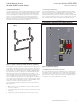
O & M Manual for the 50-400A EGSX Transfer Switch Instruction Booklet IB 70-8778 5.321 Effective November 2011 7.154 5.321 2.633 2.496 14.462 5.198 19.005 29.332 3.154 8.000 14.308 14.462 Figure 10. Dimensions and Plan View of a EGSXL24RA (in.) 10 eaton corporation www.eaton.
O & M Manual for the 50-400A EGSX Transfer Switch Instruction Booklet IB 70-8778 Effective November 2011 5.321 14.462 5.254 14.462 14.880 25.080 8.000 5.053 Figure 11. Dimensions and Plan View of a EGSX200A (in.) eaton corporation www.eaton.
O & M Manual for the 50-400A EGSX Transfer Switch Instruction Booklet IB 70-8778 5.321 Effective November 2011 5.321 14.462 5.053 14.308 Figure 12. Dimensions and Plan View of a EGSX150NSEA/EGSX200NSEA (in.) 12 eaton corporation www.eaton.com 19.005 29.196 8.
O & M Manual for the 50-400A EGSX Transfer Switch Instruction Booklet IB 70-8778 Effective November 2011 Figure 13. Dimensions and Plan View of a EGSX400NSEA (in.) eaton corporation www.eaton.
O & M Manual for the 50-400A EGSX Transfer Switch Instruction Booklet IB 70-8778 Effective November 2011 Check to ensure there are no pipes, wires, or other mounting hazards in the immediate mounting area that could create a problem. Carefully remove all packing material from the TS enclosure at the installation site.
O & M Manual for the 50-400A EGSX Transfer Switch Instruction Booklet IB 70-8778 Effective November 2011 Warning Failure to properly connect this transfer switch per NFPA 70, the national electric code, may result in product failure, fire, loss of property, loss of life, ETc. Utility Lugs Generator Lugs Utility Sensing Wire Connection Figure 16. Generator Utility Sensing Wires Connection (Typical). Step 3: Tighten all cables and wiring to specifications located on door. Load Lugs Figure 15.
O & M Manual for the 50-400A EGSX Transfer Switch Instruction Booklet IB 70-8778 Effective November 2011 4.5 Wiring WARNING POWER CONDUCTORS AND control wiring MAY HAVE VOLTAGE PRESENT THAT CAN CAUSE SEVERE PERSONAL INJURY OR DEATH. DE-ENERGIZE ALL POWER OR CONTROL CIRCUIT CONDUCTORS BEFORE BEGINNING TO PERFORM ANY WIRING ACTIVITY TO OR WITHIN THE ATS EQUIPMENT. CAUTION Utility (Source 1) Non-Critical Loads Watt-Hour Meter Utility Panel CHECK THE ATS EQUIPMENT NAMEPLATE FOR RATED VOLTAGE.
O & M Manual for the 50-400A EGSX Transfer Switch Instruction Booklet IB 70-8778 Effective November 2011 4.9 Protection Note: With feature 37, this Transfer Switch is intended as service entrance equipment.
O & M Manual for the 50-400A EGSX Transfer Switch Instruction Booklet IB 70-8778 Effective November 2011 For Catalog # EGSX200A Only Section 5: Functional Testing When protected by one of the following circuit breakers rated not more than 400 amperes, this transfer switch is rated for use on a circuit capable of delivering not more than 25,000 RMS symmetrical amperes, 240 volts maximum, but not more than the interrupting capacity of the selected circuit breaker.
O & M Manual for the 50-400A EGSX Transfer Switch Instruction Booklet IB 70-8778 Effective November 2011 warning NOTICE: The following operation will simulate an interruption of the utility power source. InsurE THE DEADFRONT IS INSTALLED PRIOR TO energizing the TRANSFER SWITCH. Step 7: Place the generator in the AUTO position. After completing the start up menus, the generator will start. A time delay will occur and the transfer switch will transfer to the GENERATOR position.
Instruction Booklet IB 70-8778 Effective November 2011 Section 6: Maintenance and Component Replacement 6.1 Introduction WARNING HIGH VOLTAGES ARE PRESENT IN AND AROUND TRANSFER SWITCH EQUIPMENT. BEFORE INSPECTING OR MAINTAINING THIS EQUIPMENT, DISCONNECT THE LINE POWER FROM THE EQUIPMENT BEING SERVICED BY OPENING AND LOCKING OUT, IF POSSIBLE, THE NEXT HIGHEST DISCONNECT DEVICE. FAILURE TO FOLLOW THIS PROCEDURE COULD CAUSE SEVERE PERSONAL INJURY AND/OR DEATH.
O & M Manual for the 50-400A EGSX Transfer Switch Instruction Booklet IB 70-8778 Effective November 2011 Figure 23. Wiring Diagram for the 100-400 Amp. EGSX TS (Shown Deenergized and Connected to Source 1). 6.2 Procedures A suggested maintenance procedure to be followed is outlined in Table 3. Table 3. Recommended Periodic Maintenance Procedures Step Action a. Make the transfer switch equipment safe for inspection and/or maintenance.
Instruction Booklet IB 70-8778 Effective November 2011 6.3 Maintenance Log Date Action Example: 01/01/04 Inspected and cleaned. 22 eaton corporation www.eaton.
O & M Manual for the 50-400A EGSX Transfer Switch Instruction Booklet IB 70-8778 Effective November 2011 6.4 Component Replacement Certain components within the TS are field replaceable. Table 4 lists the part numbers to use when ordering replacement components. To order replacement components, contact an authorized Eaton Sales Representative. Table 4. EGSX Replaceable Components.
Instruction Booklet IB 70-8778 Effective November 2011 O & M Manual for the 50-400A EGSX Transfer Switch This instructional literature is published solely for information purposes and should not be considered all-inclusive. If further information is required, you should consult an authorized Eaton sales representative. The sale of the product shown in this literature is subject to the terms and conditions outlined in appropriate Eaton selling policies or other contractual agreement between the parties.