
Full Product Manual


3
Instruction Booklet IB 70-8778
Effective November 2011
O & M Manual for the
50-400A EGSX Transfer Switch
EATON CORPORATION www.eaton.com
1.2 General Information
TSs are used to protect critical electrical loads against loss of power.
The load’s utility power source is backed up by a generator power
source. A TS is connected to both the utility and generator power
sources and supplies the load with power from one of these two
sources. In the event that power is lost from the utility power
source, the TS transfers the load to the generator power source.
Once the utility power is restored, the load is automatically trans-
ferred back to the utility power source (Figure 2).
Figure 2. Typical Load Transfer Switch (Contactor) Schematic.
An intelligence system initiates the transfer when the utility power
source fails or falls below a preset voltage. An engine start is then
initiated by the the generator and the TS transfers to the generator
power source when sufficient generator voltage is available. When
the utility power source is restored, the TS automatically transfers
back and the generator will shut down after a time delay. In the
event the utility power source fails and the generator power source
does not appear, the TS remains connected to the utility power
source until the generator power source does appear. Conversely, if
connected to the generator power source and the generator power
source fails while the utility power source is still unavailable, the TS
remains connected to the generator power source.
TSs automatically perform the transfer function, and include three
basic elements.
1. Main contacts to connect and disconnect the load to and from
the source of power.
2. Solenoids to make the transfer of the main contacts from source
to source.
3. Supervisory circuits to transfer from one source to the other.
Utility
Generator
Load
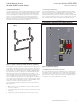
1.2.1 Design Configuration
The Eaton Residential TS is a rugged, compact design that utilizes
power contactors to transfer essential loads from one power source
to another (see Figure 3). The Residential TS contains suitable
mechanical and electrical interlock switches to eliminate the possibil-
ity of connecting the utility service to the generator output. In addi-
tion, a manual override lever is provided for the transfer function
WARNING
DO NOT MANUALLY TRANSFER THE SWITCH WHILE UNDER LOAD.
Figure 3. EGSX200A (Typical).
1.2.2 Optional Service Entrance Feature
The TS can be ordered in either a standard or service entrance (SE)
configuration. When ordered as an SE, integral overcurrent protec-
tion is built into the switch. Therefore, the TS can be installed at the
point of service entrance without the need for an upstream discon-
nect device on the utility or primary source side.