
Drawing

7
Time Current Curves TC01200002E
Effective March 2018
Series C
F-Frame
EATON www.eaton.com
.01
1
2
3
4
5
6
7
8
9
10
20
30
40
50
60
70
80
90
100
1000
900
800
700
600
500
400
300
200
2000
3000
4000
5000
6000
7000
8000
9000
10000
.02
.03
.04
.05
.06
.07
.08
.09
.1
.2
.3
.4
.5
.6
.7
.8
.9
1
3
4
5
6
7
8
9
10
20
30
40
50
60
70
80
90
100
1000
900
800
700
600
500
400
300
200
2000
3000
4000
5000
6000
7000
8000
9000
10000
.01
.02
.03
.04
.05
.06
.07
.08
.09
.1
.2
.3
.4
.5
.6
.7
.8
.9
1
Maximum total
clearing time
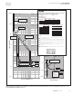
Available long delay time:
2,4,7,10,12,15,20,24 sec.
Shown @ 6 x
2,4,7,15,24 seconds
+0 / –30%
I
r
2
Application determines
end of curve
Available short delay
pick up settings
2– 8,10, x 5%12 I
r
(see Note 7)
Instantaneous
override(see Note 10)
FDE
Circuit breaker time/current curves (phase current)
Long delay (LD) and short delay (SD) with I T response
2
Available sensors( ) :I
n
80A
160A
225A
1
2 3 4
5
7
10
20 30 40 50 70 100
2 3 4
5
7
10
20
30
40
50
70
100
.5
.7
1
2 3 4
5
7
10
20 30
.5
.7
Types FDE, FDCE, HFDE circuit breakers
Notes:
1. Curve accuracy applies from –20C to +55C ambient. Temperatures above +85C cause an over-
temperature protection trip. For possible continuous ampere derating for ambient above 40C, refer
to Eaton.
2. Application frequency is 50/60 Hz.
4. The right portion of the curve is determined by the interrupting rating of the circuit breaker.
5. The left portion of the curve is shown as a multiple of the long delay setting
(Long delay pick up = 115% of ). Range is
110%
–120%.
7. The short delay pick up has nine settings/positions: 2–8, 10, 12.
9. Breakpoint back to FLAT response occurs @ 8x for upper line of the I T curve.
(corresponding to SDPU position nine) at 12x and designated as 12 . Instant aneous tolerance is
+/–20%.
12. For LD response and SD with I T response (this curve):
13. For ground fault delay response curve, see: TC01203017E
I
I
( I ) I
r
r
n
2
2
TC01203016E
12
I T
2
short delay
(see Note 8)
Minimum total
clearing time
.
.
4
.
.
.
24
.
1.15
See Note 9
12 I
i
67ms
15
7
I
80A
160A
225A
A 15A 60A 100A
B 20A 70A 10A
C 30A 80A 125A
D 40A 90A 150A
E 50A 100A 160A
F 60A 125A 175A
G 70A 150A 200A
H 80A 160A 225A
I
6. Total clearing times shown include the response times of the trip unit, the breaker opening, and the
interruption of the current.
2
8. Short delay I T band has a tolerance of +/–15%.
Breaker
type
Symmetrical RMS amperes (kA) UL/CSA
FDE
HFDE
FDCE
240 V
Interrupting ratings—50/60 Hz
65
100
200
480 V
35
65
100
600 V
18
25
35
if a current above the long delay pick up value exists for a time and then is cleared by the tripping of a
down stream device or the circuit breaker itself. A subsequent overload will cause the circuit breaker to trip
in shorter time than normal. The amount of time delay reduction is inverse to the amount of time that
completely reset memory.
i
r n
Current in Multiples of (l
r
)
Current in Multiples of (l
r
)
Current in Multiples of (l
r
)
TIME IN SECONDS
TIME IN SECONDS
1 MINUTE 1 HOUR 2 HOURS
2
8
10
7
5
4
6
3
0.001
0.01
0.1
1
1000 10000 100000
Current in Amps
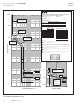
Interrupting
Rating
Determines
End of Curve
Fixed Instantaneous
Override
600V
480V
240V
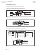
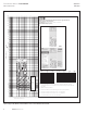
Figure 4. Types FDE, HFDE, and FDCE 225A—Long Short Delay and I
2
T—Curve Number TC01203016E
Digitrip 310+ Circuit Breaker Time/Current Curves (Phase Current)
Series C F-Frame Circuit Breakers
Catalog Types: FDE, HFDE, FDCE
Trip Unit Types: 32 (LS), 5 (LSG)
Available Sensors (I
n
): 80A, 160A, 225A
Long Delay Response (I
r
) and Short Delay with I
2
T Response Curve
Notes:
1. Curve accuracy applies from –20C to +55C ambient. Temperatures above +85C cause an overtemperature
protection trip. For possible continuous ampere derating for ambient above 40C, refer to Eaton.
2. Application frequency is 50/60 Hz.
3. There is a memory effect that can act to shorten the long delay. The memory effect comes into
play if a current above the long delay pick up value exists for a time and then is cleared by the
tripping of a down stream device or the circuit breaker itself. A subsequent overload will cause the
circuit breaker to trip in shorter time than normal. The amount of time delay reduction is inverse
to the amount of time that has elapsed since the previous overload. Approximately ve minutes is
required between overloads to completely reset memory.
4. The right portion of the curve is determined by the interrupting rating of the circuit breaker.
5. The left portion of the curve is shown as a multiple of the long delay setting.
(long delay pick up = 115% of I
r
). Range is 110%–120%.
6. Total clearing times shown include the response times of the trip unit, the breaker
opening, and the interruption of the current.
7. The short delay pick up has nine settings/positions, 2–8, 10, 12.
8. Short delay I
2
T band has a tolerance of +/–15%.
9. Breakpoint back to FLAT response occurs @ 8x I
r
for upper line of the I
2
T curve.
10. For high fault current levels an additional xed instantaneous hardware override is provided (corresponding
to SDPU position nine) at 12x (I
n
) and designated as I
i
. Instantaneous tolerance is +/–20%.
11. For LD response and SD with at response curve, see: TC01203015E.
12. For LD response and SD with I2T response (this curve): TC01203016E.
13. For ground fault delay response curve, see: TC01203017E.
14. Digitrip RMS 310+ trip units are suitable for functional eld testing with test kit Cat. No
MTST120V. For eld testing using primary injection methods, follow NEMA publication AB 4-2003.
UL/CSA rms Sym. kA, 50/60 Hz
FDE 65 35 18
HFDE 100 65 25
FDCE 200 100 25
240V 480V 600V
Breaker Type
Interrupting Rating
(I
r
) / (I
n
)
80A 160A 225A
A
B
C
D
E
F
G
H
15A 60A 100A
20A 70A 110A
30A 80A 125A
40A 90A 150A
50A 100A 160A
60A 125A 175A
70A 150A 200A
80A 160A 225A