www.eaton.
34008235EN/AC - Page 2
Introduction Thank you for selecting an EATON product to protect your electrical equipment. The Evolution range has been designed with the utmost care. We recommend that you take the time to read this manual to take full advantage of the many features of your UPS (Uninterruptible Power System). Before installing Evolution, please read the booklet presenting the safety instructions. Then follow the indications in this manual.
Introduction Pictograms Important instructions that must always be followed. Information, advice, help. Visual indication. Action. Audio signal.
Contents 1. Presentation 1.1 Standard positions ...................................................................................................................... 6 Tower models ................................................................................................................................ 6 1.2 Rack models................................................................................................................................... 6 Rear panels ..................................
1. Presentation 1.1 Standard positions Tower models Dimensions (H x W x D) in mm Evolution 650 234 x 147 x 418 Evolution 850 234 x 147 x 418 Evolution 1150 234 x 147 x 418 Evolution 1550 234 x 147 x 492 Weights in kg Evolution 650 8.4 Evolution 850 10.8 Evolution 1150 12.5 Evolution 1550 16.5 Rack models Dimensions (H x W x D) in mm Evolution 650 Rack 43.5 x 438 x 366 Evolution 850 Rack 43.5 x 438 x 512 Evolution 1150 Rack 43.5 x 438 x 512 Evolution 1550 Rack 43.
1. Presentation 1.2 Rear panels Evolution 650/850/1150/1550 1 (1) Slot for optional communication card (2) Socket for connection to AC-power source (3) 2 outlets for connection of equipment (4) RS232 communication port (5) 2 programmable outlets (1 and 2) for connection of equipment (6) USB communication port (7) Connector for remote ON/OFF and RPO (Remote Power Off) control 230V/10A Max 2 Ue/In/Eing 4 1 5 RS232 3 ROO RPO 2 6 Us/Out/Ausg I max 6.
2. Installation 2.1 Unpacking and contents check (16) Evolution UPS, tower or rack model (17) 2 connection cables for the protected equipment (18) Documentation (19) Solution-Pac CD-ROM (20) RS232 communication cable (21) USB communication cable (22) Mounting kit for 19-inch bays (rack model only, except 650 Rack) (23) System to secure power plugs (rack model only) Packing materials must be disposed of in compliance with all local regulations concerning waste.
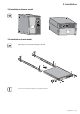
2. Installation 2.2 Installation of tower model 2.3 Installation of rack model Follow steps 1 to 4 for module mounting on the rails. The rails and necessary hardware are supplied by EATON.
2. Installation 2.4 Installation of the 650 rack model Follow steps 1 to 3 for rack mounting. The necessary hardware is supplied by EATON.
2. Installation 2.5 Communication ports Connection of RS232 or USB communication port (optional) The RS232 and USB communication ports cannot operate simultaneously. 4 6 20 RS232 1 ROO RPO 2 Us/Out/Ausg I max 6.5A 21 1 - Connect the RS232 (20) or USB (21) communication cable to the serial or USB port on the computer equipment. 2 - Connect the other end of the communication cable (20) or (21) to the USB (6) or RS232 (4) communication port on the UPS.
2. Installation 2.6 Equipment connections Check that the indications on the name plate located on the back of the UPS correspond to the AC-power source and the true electrical consumption of the total load. 1 - Disconnect the supply cable(1) (not supplied) of the equipment. 2 - Connect the cable to socket (2), then to the AC-power source. 3 - Connect the loads to the UPS using the cables (17).
3. Operation 3.1 Start-up and normal operation 1 2 14 10 11 Press button (10) for approximately 1 second. The buzzer beeps once and all the LEDs go ON simultaneously. ◗ If AC input power is available, button (10) and LED (13) are ON. The load is supplied by the AC-power source. Conditions permitting, the UPS runs a battery test, indicated by LEDs (11) and the buzzer. ◗ If AC input power is not available, button (10) and LEDs (13) and (14) are ON. The load is supplied by the UPS on battery power.
3. Operation 3.4 UPS shutdown 1 Press button (10) for approximately 2 seconds. 2 The devices connected to the UPS are no longer supplied. 10 3.5 UPS remote-control functions Evolution offers a choice between two remote control functions. RPO (Remote Power Off) allows a remote contact to be used to disconnect all the equipment connected to the UPS. Restarting the UPS requires manual intervention. ◗ ROO (Remote ON/OFF) allows remote action of button (10) to shut down the UPS.
4. Access to measurements and personalisation data Insert the Solution-Pac CD-ROM in the drive. On the first navigation screen, select "Point to Point solution" and follow the instructions on how to install the Personal Solution-Pac software. ◗ Then select "Settings", "Advanced settings" and "UPS settings". Note that the Linux/Unix/MacOS versions of Personal Solution-Pac software do not offer this possibility.
5. Maintenance 5.1 Troubleshooting Indication Diagnostic Correction 1 When the UPS is started using button (10), all the LEDs go ON once and the buzzer beeps once, then LED (14) remains ON. 2 Button (10) and LEDs (13) and (14) are The percent load is greater than ON and all the LEDs on bargraph (8) the set overload level or UPS flash. capacity. Check the power drawn by the connected devices and disconnect any non-priority devices. Check the overload level setting.
5. Maintenance Mounting the new battery module Carry out the above instructions in reverse order. ◗ To ensure safety and high performance, use only batteries supplied by EATON. care to firmly press together the two parts of the connector during remounting. ◗ Take 5.3 Replacing the battery module in the rack model Safety recommendations The battery can cause electrocution and high short-circuit currents.
5. Maintenance D - Pull the plastic tab to remove the battery block and replace it. D Mounting the new battery module Carry out the above instructions in reverse order. ◗ To ensure safety and high performance, use only batteries supplied by EATON. care to firmly press together the two parts of the connector during remounting. ◗ Take 5.
6. Appendices 6.1 Technical specifications Filter Transformer AVR Charger Inverter Battery Evolution Output power 650 / 650 Rack 850 / 850 Rack 1150 / 1150 Rack 1550 / 1550 Rack 650 VA / 420 W 850 VA / 600 W 1150 VA / 770 W 1550 VA / 1100 W AC input power input voltage ◗ Input-voltage range ◗ 50 Hz input-frequency range ◗ 60 Hz input-frequency range Single phase 220~240 V 160 V to 294 V (1) 47 Hz to 70 Hz (2) 56.
6. Appendices 6.2 Glossary 34008235EN/AC - Page 20 Backup time Time during which the load can be supplied by the UPS operating on battery power. Battery test Internal UPS test to check battery status. Booster mode Automatic UPS mode that steps up the AC voltage if it is too low, to a level above the personalised set-point, without discharging the battery. Cold start The devices connected to the UPS can be started even if AC input power is not available. The UPS operates on battery power alone.
Notes 34008235EN/AC - Page 21
www.eaton.