
Installation Manual

2
Installation Instructions for EHD, EDB, EDS, ED, EDH, EDC, FDB, FD,
HFD, FDC, HFDDC Circuit Breakers and Molded Case Swiches
EATON CORPORATION www.eaton.com
WARNING
DO NOT ATTEMPT TO INSTALL OR PERFORM MAINTENANCE ON EQUIP-
MENT WHILE IT IS ENERGIZED. DEATH, SEVERE PERSONAL INJURY OR
SUBSTANTIAL PROPERTY DAMAGE CAN RESULT FROM CONTACT WITH
ENERGIZED EQUIPMENT. ALWAYS VERIFY THAT NO VOLTAGE IS PRESENT
BEFORE PROCEEDING WITH THE TASK, AND ALWAYS FOLLOW GENERALLY
ACCEPTED SAFETY PROCEDURES.
EATON IS NOT LIABLE FOR THE MISAPPLICATION OR MISINSTALLATION
OF ITS PRODUCTS.
The user is cautioned to observe all recommendations, warnings
and cautions relating to the safety of personnel and equipment, as
well as all general and local health and safety laws, codes, and pro-
cedures.
The recommendations and information contained herein are based
on Eaton experience and judgment, but should not be considered to
be all-inclusive or covering every application or circumstance which
may arise. If any questions arise, contact Eaton for further informa-
tion or instructions.
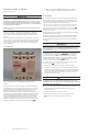
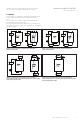
1. Introduction
Figure 1. Model D Series C Circuit Breaker and Molded Case
Switches
The F-Frame Series C circuit breakers (Fig. 1) are rated from 15A to
225A (150A for 1 pole versions)
continuous current and are available
as thermal-magnetic circuit breakers and molded case switches.
(Molded case switches are available rated at 100A, 150A , and
225A.) Circuit breakers are listed in accordance with Underwriters
Laboratories, Inc. Standard UL489, and satisfy the (P1) requirements
of the International Electrotechnical Commission Recommendation
No. IEC 157-1. Molded case switches are listed in accordance with
UL489. For this publication, the term circuit breaker also includes
molded case switches and F-Frame is used to cover all of the circuit
breakers and molded case switches associated with this
2. Installation
The installation procedure consists of inspecting and mounting the
circuit breaker, connecting and torquing the line and load termina-
tions, and attaching terminal shields or barriers, when supplied. To
install the circuit breaker perform the following steps:
ote:N The F-Frame circuit breakers are factory sealed. UL489 requires that
internal accessories be installed at the factory. Where local codes and stan-
dards permit and UL listing is not required, internal accessories can be
installed. Accessory installation should be done before the circuit breaker is
mounted and connected.
Mounting hardware and unmounted terminations (where required)
are supplied in separate packages.
2-1. Make sure that the circuit breaker is suitable for the installation
by comparing nameplate data with system requirements. Inspect
the circuit breaker for completeness and check for damage before
mounting.
WARNING
BEFORE MOUNTING THE CIRCUIT BREAKER IN AN ELECTRICAL SYSTEM,
MAKE SURE THERE IS NO VOLTAGE PRESENT WHERE WORK IS TO BE
PERFORMED. THE VOLTAGES IN ENERGIZED EQUIPMENT CAN CAUSE
INJURY OR DEATH.
2-2. Depending on the equipment the circuit breaker
can be mounted using di
erent styles of hardware. The following
steps describe how to mount the circuit breaker using standard
hardware. When special hardware is needed (for example, with the
electrical operator), the instruction
describing the accessory
also describes the special mounting arrangements.
ote:N Before mounting the circuit breaker, check if the termination devices
should be installed
See terminations instructions.
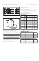
2-3. To mount the circuit breaker, perform the following steps:
a. For individual mounting panels, make sure that mounting panel is
predrilled using bolt drilling plan (Fig. 2). For panelboard mounting,
only load end support mounting holes are required. For deadfront
cover applications make sure panel cover is cut out to correct
escutcheon dimensions (Fig.3).
CAUTION
DO NOT EXCEED CONNECTOR/BUS CAPACITY IN EATON POWER LINE
3A AND 4 PANELS. USE CONNECTOR KIT KPRL3AFD3 (3-POLE) AND
KPRL3AFD2 (2-POLE) IN PANEL TYPE PRL3A AND KPRL4FD (3-POLE) AND
KPRL4FD2 (2-POLE) IN PANEL PRL4.
b. If circuit breaker includes factory installed internal accessories,
make sure accessory wiring can be reached when the circuit
breaker is mounted.
c. Position circuit breaker on mounting surface.
d. Install mounting screws, washers, and nuts. Tighten screws
y, but do not exceed 28 pound-inches (3.16 N.m)
Instruction Leaet IL 29C102I
Eective December 2013