
Cut Sheet


V4-T2-150 Volume 4—Circuit Protection CA08100005E—August 2015 www.eaton.com
2
2
2
2
2
2
2
2
2
2
2
2
2
2
2
2
2
2
2
2
2
2
2
2
2
2
2
2
2
2
2.3
Molded Case Circuit Breakers
Series C
FDE 310+ Specifications
Description Specification
Trip Unit Type Digitrip RMS 310+
Breaker Type
Frame designation FD
Frames available 80 A, 160 A 225 A
Continuous current range (A) 15–225 A
Ground fault pickup (A) 16–225A
Interrupting capacities at 480Vac (kAIC) 35, 65, 100
100% rated No
Protection
Ordering options LS, LSI, LSG, LSIG
Arcflash reduction maintenance system (or maintenance mode) No
Interchangeable trip unit No
High load alarm (suffix B20) No
Ground fault alarm with trip (suffix B21) No
Ground fault alarm, no trip (suffix B22) No
Zone selective interlocking (suffix ZG) LSI, LSIG
Cause of trip indication Yes
Thru-cover accessories No
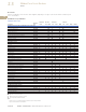
FDE 310+ Adjustability Specifications
Notes
1
Not available for FD. Independently adjustable Ii setting available in LG, NG and
RG ALSI and ALSIG trip units.
2
Maintenance Mode not available for FD frames. It is available for KD, LD, MDL, LG, NG
and RG.
FD Frame
310+ Settings 80 A 160 A 225 A
I
r
= continuous current or long delay pickup (amperes)
(All 310+)
I
r
A 1560100
B 2070110
C 3080125
D 4090150
E 50 100 160
F 60 125 175
G 70 150 200
H (= I
n
) 80 160 225
t
r
= long delay time (seconds)
(All 310+)
Position 1 2 2 2
Position 2 4 4 4
Position 3 7 7 7
Position 4 10 10 10
Position 5 12 12 12
Position 6 15 15 15
Position 7 20 20 20
Position 8 24 24 24
I
sd
(x I
r
) = short delay pickup
(All 310+)
Position 1 2x 2x 2x
Position 2 3x 3x 3x
Position 3 4x 4x 4x
Position 4 5x 5x 5x
Position 5 6x 6x 6x
Position 6 7x 7x 7x
Position 7 8x 8x 8x
Position 8 10x 10x 10x
Position 9 12x 12x 12x
t
sd
= short delay time I
2
t (milliseconds)
(LS, LSG)
Fixed 67
at10x
67
at10x
67
at10x
t
sd
= short delay time flat (milliseconds)
(LSI, LSIG)
Position 1 Inst Inst Inst
Position 2 120 120 120
Position 3 300 300 300
I
g
= gound fault pickup (amperes)
(LSG, LSIG)
Position 1 16 32 45
Position 2 24 48 67
Position 3 32 64 90
Position 4 48 96 135
Position 5 64 128 180
Position 6 80 160 225
t
g
= ground fault delay time (milliseconds)
(LSG, LSIG)
Position 1 Inst Inst Inst
Position 2 120 120 120
Position 3 300 300 300
Independently Adjustable Instantaneous (I
i
) setting
1
Maintenance Mode pickup (2.5 x I
n
) (amperes)
2