® Genesys™ Ergonomic Workstation—G110 & G111 Series Eaton® Profile ® Eaton Profile® Genesys™ Dual-Lift Ergonomic Workstation G110 and G111 Series ® Eaton Raised Floor Grommets—FG76, FG118 ◦ ◦ 90 and 120 Dual-Lift Ergonomic Workstations Installation Guide
© Copyright 2011 Eaton Corporation, Worcester, MA, USA. All rights reserved. Information in this document is subject to change without notice. No part of this document may be reproduced or transmitted in any form or by any means, electronic or mechanical, for any purpose, without the express written consent of Eaton. Eaton and Profile are registered trademarks and Genesys is a trademark of Eaton Corporation or its subsidiaries and affiliates. Phillips is a registered trademark of Phillips Screw Company.
Table of Contents About this Guide Audience General Conventions Documentation vii vii viii 1 Before you Begin Introduction Important Safety Information Site Preparation Tools you Will Need Fasteners you Will Be Using Washers and Grommets you Will Be Using 1 1 1 2 2 3 2 Pre-Installation Preparation and Planning Prerequisites Installation Overview/Checklist Tools you Will Need Fasteners you Will Be Using Unpack the Box Contents Workstation Components Lifts Covered in this Manual 3 5 5 5 5 6 7 8 Install
5 Service and Support Troubleshooting Lift Freezes Error Code Appears on Control Pad Technical Support Sales Representatives Local US Representatives Eaton Worcester Office Latin America, Central/South America & The Caribbean International Distribution Documentation wwww.eaton.
About this Guide This document describes how to install the Profile® Genesys™ Dual-List Ergonomic Workstation. The Profile Genesys Workstation is an ergonomic solution designed for command and control environments such as Emergency Operations Centers, Network Operations Centers, Process Control Environments, Medical Imaging Reading Rooms, and more. Audience This document is intended for installers and/or qualified personnel who are installing the Profile Genesys Dual-Lift Ergonomic Workstation.
About this Guide Documentation This document can be obtained from our website at http://www.wrightline.com by following this procedure: 1. 2. 3. Click on the “Library” icon. Click on the “Installation Manuals” link, and then select the “Command/Control” option. Under the “Command/Control” section, click on the “Profile Advanced Console System” option.
Chapter 1 Before you Begin Introduction The Profile Genesys Dual-Lift Ergonomic Workstation is an ergonomic solution designed for command and control environments such as Emergency Operations Centers, Network Operations Centers, Process Control Environments, Medical Imaging Reading Rooms, and more. This workstation solution accommodates all computing, networking, and electrical cabling required in a modern command and control environment.
Before you Begin Tools you Will Need The following tools are required to successfully install the workstation.
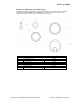
Before you Begin Washers and Grommets you Will Be Using Following is an illustration of the washers and grommets that are provided in the Lift assembly box (provided in kit labeled PROKIT43-thru-PROKIT46). Front and side views are shown. For a complete list of parts, refer the section, “Unpack the Box Contents.” Item Description Part Number Washers and Plugs 4 9 6 13 Lock washer, helical 3/8” W Series washer 1.
Chapter 2 Pre-Installation Preparation and Planning This chapter describes the preparation and planning involved prior to installing the Profile Genesys Dual-Lift Ergonomic Workstation. Prerequisites The core-to-core assembly must be complete before the ergonomic workstation installation can occur. For instructions on how to install the core-to-core assembly, refer to the Profile Flat Panel Console System Installation Manual at our website, http://www.wrightline.com.
Pre-Installation Preparation and Planning Unpack the Box Contents Before you begin the installation and assembly process, ensure that the following parts are included in your shipment. Refer to the illustration on the next page for a diagram of all system components included in the PROKIT46 assembly (60” x 60” workstation). If any parts are missing, then contact Technical Support at to.support@eaton.com.
Pre-Installation Preparation and Planning Workstation Components The following diagram illustrates all components that are included in the Profile Genesys Dual-Lift Ergonomic Workstation shipment. Refer to the table on the previous page for a description and quantity of each component. 7 Eaton Profile Genesys Dual-Lift Ergonomic Workstation Installation wwww.eaton.
Pre-Installation Preparation and Planning Lifts Covered in this Manual The following table lists the Profile Genesys Ergonomic Lifts that are covered in this manual.
Chapter 3 Installing the Dual-Lift Workstation Introduction This chapter describes how to install the components of the dual-lift workstation.
Installing the Ergonomic Workstation Install the Rear Lift Column Assembly Follow these procedures to assemble the rear lift column assembly. Attach Lift Column to Base Assembly Follow these instructions to attach the rear lift column to the base. NOTE: This procedure requires a team of two people to support and stabilize the lift column and base until the fasteners are secure and the assembly is resting on the base. Raise the leveling feet on the base cover to 3/4” before you begin the assembly process.
Installing the Ergonomic Workstation NOTE: Keep the assembly vertical at all times. Do not fasten base cover at this time. Step (4x) Base Lift Column 5. Tighten the screws in an X pattern as shown below, being careful not to over-tighten. The lift column is made of aluminum and the screw holes are susceptible to being easily stripped. Step 6. Flip over the assembly so that the base rests on the floor. Move and position the assembly close to the final installation location.
Installing the Ergonomic Workstation Install the Front Lift Column Assembly Follow these procedures to install the front lift column assembly. Attach Leg Assembly to Feet Follow these instructions to attach the foot assembly (left and right) to its respective DL6 leg assembly (left and right). NOTE: The foot bracket and the top of the leg assembly must both be oriented to its respective foot - left with left and right with right.
Installing the Ergonomic Workstation Attach Leg Assemblies to Base Follow these instructions to attach the left and right leg assembly to its respective base support. 1. Align the right leg assembly with the right base support. Leg Assembly Support Cover Leg Assembly Base Supports (Left and Right) 2. Insert eight Phillips head thread form screws (66714) and tighten as shown below. Step Step (8x) 13 3. Repeat step 1 to align the left leg assembly to the left base support. 4.
Installing the Ergonomic Workstation Attach Leg and Base Support Covers Follow these instructions to attach the base support cover (left and right) to its respective base support (left and right). 1. Attach the base support cover to the right base support. 2. Insert and tighten six Phillips head thread form screws (66714) through the base support cover, securing the cover to the base support as illustrated below.
Installing the Ergonomic Workstation 5. Insert four Phillips head thread form screws (66714) in the screw holes on the lift base cover and tighten (see the illustration below). 6. Re-install the two lift column screws you removed and retained earlier to the base as shown below. Step Lift Base Cover Step (4x) Step (2x) Step Step You have successfully attached the leg and base covers for the Profile Genesys Ergonomic Workstation.
Installing the Ergonomic Workstation Level Assembled Components Follow these instructions and refer to the illustration below to level the components that have been assembled at this point, including the leg assemblies as well as the lift column. WARNING: Failure to follow these instructions may result in improper installation and potential product damage. 1. Make sure the lift column base levelers are extended at least 3/4” prior to leveling.
Installing the Ergonomic Workstation Attach Lower Frame Follow these instructions and refer to the illustration below to attach the workstation support frame to the assembled components. It is very important to perform these instructions in the sequential order noted here; otherwise, failure to do so may result in personal injury or product damage. CAUTION: To prevent personal injury and product damage, two or more people are required to perform the following procedure. 1.
Installing the Ergonomic Workstation 7. Level and align the lower frame, then tighten all inserted screws in the sequence noted here and illustrated below. 8. Tighten four (4) screws on the leg assemblies (DL6). 9. Tighten two (2) side screws on lift column (DL2). Ensure unit is properly aligned, level and plumb 90 degrees to all lifts and legs. 10. Tighten one front screw on the lift column (DL2). Step Step (4x) Step (2x) Step (1x) Step wwww.eaton.
Installing the Ergonomic Workstation Attach Workstation Support Follow these instructions and refer to the illustration below to attach the workstation support to the assembled components. CAUTION: To prevent personal injury and product damage, two or more people are required to perform the following procedure. 1. Align the workstation support over the left and right leg assemblies. 2.
Installing the Ergonomic Workstation Install Rear Surface and Trim Assembly Follow these instructions to install the rear surface and trim assembly. Attach Rear Surface Support Beam Follow these instructions and refer to the illustration below to attach the rear surface support frame. NOTE: This procedure requires a team of two people to align the beam and stabilize it until the fasteners are secure. 1. Align the rear surface support beam over the top of the lift column. 2.
Installing the Ergonomic Workstation Attach Center Column Cable Chains Follow these instructions to attach the cable chain bracket and chains. 1. Place the cable chain support bracket to the bottom rear of the rear surface support beam. Rear Surface Support Beam Step Step (6x) Step (6x) Step Cable Chains Step Step (6x) 21 2.
Installing the Ergonomic Workstation Drill Holes for Flat Panel Display Support Before completing this procedure, refer to the project-specific bill of materials (BOM) and CAD drawings for FPD mount configuration. Individual component installation / assembly instructions for bow arrays and Centris® Cup can be found on the website under their respective part numbers.
Installing the Ergonomic Workstation 3. From the bottom of the rear surface, drill two holes to approximately .250” diameter through the bottom backer material. This will prevent chipping of backer material. 4. From the top rear surface, use the pilot holes to drill two 2.50” holes down through the laminate and completely through the deck using a 2-1/2” diameter hole saw. Attach Rear Surface Trim Panels Follow these instructions and refer to the illustration below to attach the rear surface trim panels.
Installing the Ergonomic Workstation Attach Rear Surface Follow these instructions and refer to the illustration below to attach the rear surface to the rear surface support beam. 1. Align the rear surface above the rear surface beam using the flat panel display poles and/or grommet opening to help with alignment. 2. From the bottom of the rear surface, insert 17 Phillips head screws (62071) through the support beam into the bottom of the surface and tighten.
Installing the Ergonomic Workstation Install User Surface and Components Follow these instructions to install the user surface and components. Attach User Surface Follow these instructions to attach the user surface to the support frame. 1. Align the pre-drilled holes in the bottom of the user surface with the openings in the support frame. 2. Insert the Phillips head wood screws (62071) and tighten. The number of screws may vary depending on the lift size.
Installing the Ergonomic Workstation Check and Adjust Workstation to Maintain Proper Workstation Spacing Follow these instructions to check and adjust the workstation setting (if necessary) to ensure proper spacing between the user surface and the rear surface of the workstation. To check the spacing between the user and rear surfaces, do the following: 1. Extend the user and rear surfaces to their highest setting. 2. Measure the gap between the surfaces to be 1.5”. 3.
Installing the Ergonomic Workstation Attach Left Cable Chain to User Surface Follow these instructions and refer to the figure below to assemble and attach the left cable chain to the user surface. 1. From below the user surface, attach the 53-link cable chain (97632) using two Phillips head screws (62071) to the surface. 2. From behind the assembly, attach the cable chain to the lower frame using three Phillips head machine screws (18618).
Installing the Ergonomic Workstation Attach Lift Control Box and Operator Control Pad Follow these instructions and refer to the figure below to attach the power control box and power control pad to the bottom of the user surface. 1. From underneath the user surface, attach the lift control box (90066) to the center rear section of the surface. Insert four Phillips wood screws (62071) and tighten. User Surface Power Control Box Step (4x) 2.
Installing the Ergonomic Workstation Route Cables Follow these instructions for an overview on how to route cables through the assembled components to a power source. These instructions are intended to provide general guidelines only since configurations may vary. To route cables, do the following: 1. Route the power control cable from the power control switch (96239) through the channel in the workstation support frame to the control box (90066). When routing cables, adhere to these guidelines: a. b. c.
Installing the Ergonomic Workstation 3. Connect the DL6 cable to Port 1 as shown below. 4. Connect the other DL6 cable to Port 2 as shown below. 5. Connect the DL2 cable to Port 3 as shown below. 6. Connect the power cable to the power outlet as shown below. 7. Connect the controllers to the controller port as shown here. Port Connections Detail IMPORTANT: Note the connection port assignment. The workstation will not function unless the lifts are plugged into the correct ports as shown here. 8.
Installing the Ergonomic Workstation Install the Rear Cover Once all the cables have been routed, you will need to install the rear cover to the rear surface. To install the rear cover to the rear surface, do the following: 1. Attach the rear cover (21616X) to the rear surface by inserting three (3) #10A x 1” Phillips pan head screws (62071) through the rear cover and into the rear surface and tighten. Rear Surface Rear Cover Step (3x) 2. The rear cover installation is now complete.
Installing the Ergonomic Workstation Initialize the System To initialize the lift, do the following: 1. On the control pad, press the Down Arrow button until the lift column lowers to the “end-stop” position”. Workstation Model Shown for Illustrative Purposes Only 2. If the controls are not working properly, then refer to the DeskPower DB4/DL4 Systems Guide to ensure the control pad has been properly installed. Refer to the “Documentation” section of this manual for document location.
Installing the Ergonomic Workstation Installation Options for the G111 Series This section provides instructions on installing the Eaton Profile Genesys G111-Series Ergonomic Workstation with keyboard tray. Skip this section if you are not installing this product. Attach Keyboard Tray If you ordered the keyword tray, then follow these instructions to attach the keyboard tray to the user surface. 1.
Chapter 4 Aligning the Workstation to the Core Now that the Profile Genesys Dual-Lift Ergonomic Workstation has been successfully installed, you will need to align the workstation to the core as documented below. To install additional system components such as flat panel displays, and so on, refer to the Profile® Flat Panel Console System Installation Manual for detailed instructions. To align the workstation to the core, do the following: 1.
Aligning Workstation to the Core 4. Connect the lift with connector base to the core via four (4) #1/4-20 screws (53956) and #1/4-20 Kep nuts (18209 ). Step Genesys-Compatible Inside Skin (Fabric, Laminate or Steel) 90º Compound Corner Shown Connector Cover Step (4x) Step Connector Base (G431A903) Genesys Lift (Shown for Reference Only) 5. Install the grommet in the grommet opening in the core as shown below. 6.
Chapter 5 Service and Support If you have any problems with installing or using this product, follow these troubleshooting tips or contact us using one of the methods provided. Troubleshooting If a problem occurs with the system, refer to the “Troubleshooting” section of the Eaton Profile Genesys Ergonomic Workstation Operator’s Manual for troubleshooting tips and corrective actions.
Service and Support 2. If the controls are still not working properly, then do one of the following: Refer to the Eaton Profile Genesys Dual-Lift Ergonomic Workstation Operator’s Manual for troubleshooting tips and corrective actions. Refer to the DeskPower DB4/DL4 Systems Guide to ensure the control pad has been properly installed. See the “Documentation” section of this manual for document location. Contact Eaton for Technical Support assistance.
Service and Support Latin America, Central/South America & The Caribbean Carla Hauschildt Eaton HC20 Box 10723 Juncos, PR 00777 Tel: (787)547-2627 Fax: (508)365-6042 International Distribution Canada TAB Technical Environments 130 Sparks Avenue Willowdale, ON M2H 2S4 Tel: 800-667-4020 Fax: 888-257-5205 Europe ICTroom Company BV Tokyostraat 27-29 1175 RB Lijnden Postbus 9185 1006 AD Amsterdam The Netherlands Tel: 31-(0)-20-820-3000 Fax: 31-(0)-20-820-3010 Malaysia Quantum Special Sdn Bhd 2-2 Jalan USJ 1/1B
Service and Support Tokyo Rinbard Co., Ltd. Jono Bldg. II 3F 17-1 Nihonbashi-Odenmacho, Chuo-ku Tokyo 103-0011 Japan Tel: 81-3-5651-8123 Fax: 81-3-5651-8170 Documentation For documentation pertaining to this product and related Eaton products, visit our website at http://www.wrightline.com. www.eaton.
To contact an Eaton salesperson or local distributor, please visit www.eaton.com/wrightline or call 800-225-7348. Eaton Corporation Electrical Sector 1111 Superior Ave. Cleveland, OH 44114 United States 877-ETN-CARE (877-386-2273) Eaton.