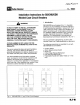
Cutler-Hammer fp FISH 7 1.L. 15547 Installation Instructions for GB/GHB/GDB Molded Case Circuit Breakers A WARNING DO NOT ATTEMPT TO INSTALL OR PERFORM MAINTENANCE ON EQUIPMENT WHILE IT IS ENERGIZED. SEVERE PERSONAL INJURY, DEATH, OR SUBSTANTIAL PROPERTY DAMAGE CAN RESULT FROM CONTACT WITH ENERGIZED EQUIPMENT. ALWAYS VERIFY THAT NO VOLTAGE IS PRESENT BEFORE PROCEEDING WITH THE TASK, AND ALWAYS FOLLOW GENERALLY ACCEPTED SAFETY PROCEDURES.
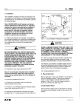
Page 2 2. Installation The installation procedure consists of inspection and mounting the circuit breaker, connection and torquing the terminations. To install the circuit breaker, perform the following steps. Note: GB/GHB/GDB circuit breakers are factory sealed. Underwriters Laboratories, Inc. Standard requires that internal accessories be installed at the factory. Where local codes and standards permit and UL listing is not required, internal accessories can be field installed.
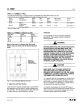
LL. 15547 Page 3 TABLE 2-1. TERMINAL TYPES For Load-side terminal only. Line-side connection is extended tang which bolts directly to bus bar. Load terminals are UL listed as suitable for wire type and size given below. Circuit Terminal Bestrew Wire AWG Metric Wire Torque Breaker Type Material Head Type Wire Range {mm?) Value Amps. Type Range 15-20 Clamp Slotted Circuit #1410 1.5.
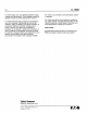
Page 4 4-3. Check base, cover, and operating handle for cracks, chipping, and discoloration. Circuit breakers should be replaced if cracks or severe discoloration is found. 4-4. Check terminals and connectors for looseness or signs of overheating. Overheating will show as discoloration, melting, or blistering of conductor insulation, or as pitting or melting of conductor surfaces due to arcing, if there is no evidence of overheating or looseness, do not disturb or tighten the connections.