
Cut Sheet


43
Technical Data TD01701005E
Effective March 2015
IEC low voltage busway
Pow-R-Way III
EATON www.eaton.com
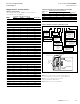
Construction drawing
48.00
(1219.2)
2500 A 30 4W
Same Elevation
See Drawing
BVC1012 Line 5
See Drawing
BVC1004 Line 15
A08
8.00
(203.2)
A10
6.00
(152.4)
Plug-In Unit
All Floors
1600 A 30 4W
2 of
6 .00 – 5/8
2.00
–
1.00
Outdoor
Duct
Indoor
Duct
F
111.44
(2830.6)
0.45
(11.4)
96.00
(2438.4)
30.00
(762.0)
120.0
(3048.0)
30.00
(762.0)
120.0
(3048.0)
6.00
(152.4)
150.0
(3810.0)
150.0
(3810.0)
30.00
(762.0)
30.00
(762.0)
15.00
(381.0)
18.00
(457.2)
35.00
(889.0)
293.00
(7442.2)
240.00
(6096.0)
29.00
(736.6)
15.00
(381.1)
25.63
(651.0)
24.00
(609.6)
52.00
(1320.0)
36.00
(914.4)
12.00
(304.8)
39.00
(990.6)
44.00
(1117.6)
25.00
(635.0)
17.00
(431.8)
6.00
(152.4)
4.38
(111.3)
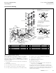
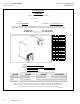
G
A
B
C
N
16.14
(409.9)
2 – .25 x 4.25 (6.35 x 108.0) Copper/Phase
2 – .25 x 4.25 (6.35 x 108.0) Copper/Neutral
Duct Weight = 42 Lb/Ft
Color = ANSI 61 Gray
Indoor/Outdoor
3200 Ampere, 3-Phase Copper, 227/480 Volts
4-Wire, Housing Ground, 100% Neutral
4.38
(111.3)
G
A
B
C
N
7.38
(187.5)
1 – .25 x 4.25 (6.35 x 108.0) Copper/Phase
1 – .25 x 4.25 (6.35 x 108.0) Copper/Neutral
Duct Weight = 21 Lb/Ft
Color = ANSI 61 Gray
Indoor/Outdoor
1600 Ampere, 3-Phase Copper, 227/480 Volts
4-Wire, Housing Ground, 100% Neutral
A07
A01
A02
A03
A04
A06
A09
A11
A12
A13
A12
A12
A12
A14
A15
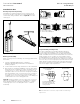
Style No.
Item Description or S.O. No. Req.
A01 XFMR Throat LVB01234 – U01 1
A02 Elbow LVB01234 – A02 1
A03 Wall Flange BVC0299G11 1
A04 Elbow Flange LVB01234 – A04 1
A05 Hanger BVD0301G12 2
A06 Flange Elbow LVB01234 – A06 1
A07 Elbow LVB01234 – A07 1
A08 29.0 Inches (736.6 mm) Length LVB01234 – A08 1
A09 120.0 Feet (3048.0 mm) Length LVB01234 – A09 2
Style No.
Item Description or S.O. No. Req.
A10 Elbow LVB01234 – A10 1
A11 Floor Flange BVD0299G06 3
A12 30 Inches (726.0 mm) Length LVB01234 – A12 3
A13 120.0 Feet (3048.0 mm) Length LVB01234 – A13 2
A14 96.0 Feet (2438.4 mm) Length LVB01234 – A14 1
A15 End Closer BVD0156G08 1
A16 Hanger BVD0300G12 3
A17 Hanger BVD0300G15 4
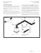
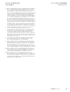
Figure 64. Sample installation drawing
After the approval process and prior to shipment of the busway
from the factory, the installer will receive a set of construction
drawings. A sample is illustrated in Figure 64 above. The drawings
will contain a complete layout of the entire installation and a bill of
material that includes:
1. The item number of each section that can be correlated with
the drawing.
2. A description of each section.
3. The style number or shop order number of each section.
4. The quantity of each section or style number required.
5. The height, width, and weight (per ft) of each ampere rating.
6. Location of the “T” and “F” markings on the busway.
7. Flange reference drawings.
8. Switchgear locations and orientation.
9. Wall and floor locations.
10. The length of each section.
11. The location of any sections that have been designated as
“Field Fit” pieces (see Page 45).
The installer should review this drawing prior to and during the
installation process. Please note that plug-in units are generally
not shown on a construction drawing. The installer will also receive
installation instruction leaflets, and operation and maintenance
manuals with the drawings.