Eaton® Intelligent Power® Manager (IPM) User’s Guide
Eaton is a registered trademarks of Eaton Corporation or its subsidiaries and affiliates. Google Chrome is a trademark of Google, Inc. HyperTerminal is a registered trademark of Hilgraeve. Linux is a registered trademark of Linus Torvalds in the United States, other countries, or both. Microsoft, Internet Explorer, Vista, and Windows are registered trademarks of Microsoft Corporation in the United States and other countries. Mozilla and Firefox are registered trademarks of the Mozilla Foundation.
Class A EMC Statements FCC Information This equipment has been tested and found to comply with the limits for a Class A digital device, pursuant to part 15 of the FCC Rules. These limits are designed to provide reasonable protection against harmful interference when the equipment is operated in a commercial environment.
Special Symbols The following are examples of symbols used on the UPS or accessories to alert you to important information: RISK OF ELECTRIC SHOCK - Observe the warning associated with the risk of electric shock symbol. CAUTION: REFER TO OPERATOR'S MANUAL - Refer to your operator's manual for additional information, such as important operating and maintenance instructions. This symbol indicates that you should not discard waste electrical or electronic equipment (WEEE) in the trash.
Table of Contents 1 2 INTRODUCTION . . . . . . . . . . . . . . . . . . . . . . . . . . . . . . . . . . . . . . . . . . . . . . . . . . . . . . . . . . . . . . . . . . . . . . . . 1 Compatibility . . . . . . . . . . . . . . . . . . . . . . . . . . . . . . . . . . . . . . . . . . . . . . . . . . . . . . . . . . . . . . . . . . . Eaton Devices . . . . . . . . . . . . . . . . . . . . . . . . . . . . . . . . . . . . . . . . . . . . . . . . . . . . . . . . . . . . . . Serial Line Devices . . . . . . . . . . .
Table of Contents Automatic Data Purge . . . . . . . . . . . . . . . . . . . . . . . . . . . . . . . . . . . . . . . . . . . . . . . . . . . . . . . . . . . . Manage the Cisco UCS Manager Component. . . . . . . . . . . . . . . . . . . . . . . . . . . . . . . . . . . . . . . . . . Enabling the Component . . . . . . . . . . . . . . . . . . . . . . . . . . . . . . . . . . . . . . . . . . . . . . . . . . . . . . Add the Component . . . . . . . . . . . . . . . . . . . . . . . . . . . . . . . . . . . . . . . . .
Table of Contents Power Source View . . . . . . . . . . . . . . . . . . . . . . . . . . . . . . . . . . . . . . . . . . . . . . . . . . . . . . . . . . . . . . Shutdown Sequence . . . . . . . . . . . . . . . . . . . . . . . . . . . . . . . . . . . . . . . . . . . . . . . . . . . . . . . . . . . . . 6 7 8 68 69 ADVANCED MANAGEMENT . . . . . . . . . . . . . . . . . . . . . . . . . . . . . . . . . . . . . . . . . . . . . . . . . . . . . . . . . . . . . 71 Nodes Settings . . . . . . . . . . . . . . . .
Table of Contents 9 10 USER DRIVERS . . . . . . . . . . . . . . . . . . . . . . . . . . . . . . . . . . . . . . . . . . . . . . . . . . . . . . . . . . . . . . . . . . . . . . . . . 109 User Drivers Editor . . . . . . . . . . . . . . . . . . . . . . . . . . . . . . . . . . . . . . . . . . . . . . . . . . . . . . . . . . . . . . User Drivers Page . . . . . . . . . . . . . . . . . . . . . . . . . . . . . . . . . . . . . . . . . . . . . . . . . . . . . . . . . . . User Driver Editor Dialog . . . . . . . .
Table of Contents Deploying a Virtual Appliance in VMware vSphere . . . . . . . . . . . . . . . . . . . . . . . . . . . . . . . . . . . . . . Configuring a Virtual Appliance . . . . . . . . . . . . . . . . . . . . . . . . . . . . . . . . . . . . . . . . . . . . . . . . . . . . . Setting Security for a Virtual Appliance . . . . . . . . . . . . . . . . . . . . . . . . . . . . . . . . . . . . . . . . . . . . . . . Basic Firewall Configuration . . . . . . . . . . . . . . . . . . . . . . . . . . . . . . . . . .
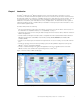
Chapter 1 Introduction The Eaton® Intelligent Power® Manager (IPM) is a power environmental device supervision tool for IT environments. The Eaton IPM delivers a global view across the network from any PC with an Internet browser.
Introduction Compatibility Eaton has tested the compatibility of the Eaton IPM with the following devices and applications. NOTE If a device doesn’t support the Quick Scan feature, it can be supervised if Address Scan or Range Scan operations are performed. See “Discover Nodes Connected on the Network” on page 17 for more information. Eaton Devices Table 1.
Introduction Table 1.
Introduction Other Network Devices The Eaton IPM is compatible with the following other network device (see Table 3). Table 3. Other Devices Eaton Equipment Designation Card Proxy Features HP UPS Network Module Minislot (AF465A) Network Card Quick Scan Dell Network UPS Card (H910P) Network Card IBM UPS Network Management Card (46M4110) Network Card Quick Scan All IETF MIB enabled UPSs (RFC1628), such as Liebert (Standard IETF UPS MIB 1.3.6.1.2.1.33.
Introduction Test conditions during 40 hours: l 1300 nodes (including ~50 real), mainly Eaton IPMs, and Network Management Cards. l Average CPU load: 20~30% l Memory load: 200~300MB Test with Machine 2 (typical PC) l CPU: Intel Core™ 2 Duo 6600 @2.4GHz l Memory: 2Go DDR2 l HDD: 1 HDD 220 GB 7200 rpm l OS: Microsoft® Windows Vista® Enterprise 32 bits Test conditions during 40 hours: l 1000 nodes (including ~50 real), mainly Eaton IPMs, and some NSM and Network Management Card.
Introduction Troubleshooting HTML pages Cannot display the UPS properties page. HTTP 404 error with IE. Solution: Check the URL entered. https://:4680/ - or http://:4679/ Terms This section provides related terms and definitions. IP Address When Transmission Control Protocol / Internet Protocol (TCP/IP) is installed on a computer, an Internet Protocol (IP) address is assigned to the system.
Introduction l Lib USB l Net SNMP The full license version for each of these projects is available from Eaton IPM using the Settings > System > About selection path. Java Licensing Eaton's advanced software (infra connector) uses the OSGI framework technology. All the constituent modules of the new features (virtualization, storage, Cisco UCS) are based on OpenJDK (Open Java Development Kit, which is a free and open source implementation of the Java Platform).
Introduction 8 Eaton Intelligent Power Manager (IPM) User’s Guide v1.
Chapter 2 Installation This chapter provides Eaton Intelligent Power Manager (IPM) installation prerequisites and quick start installation procedures. Procedures for uninstalling and upgrading the product are also included. NOTE Please refer to the following installation information for operating system compatibility: http://pqsoftware.eaton.com/install/common/eaton_os_compatibilities_aa.
Installation JRE Prerequisites For all features correlated to the infrastructure connector (like VMware, UCS, NetApp) a JRE must be installed on the system hosting Eaton IPM (see “JRE Installation” on page 15). If this prerequisite is not installed, only virtualization features are available, such as the legacy API for VMware connectors. Table 5. JRE Virtualization, Storage, and ServerCitrix XenCenter Virtualization, Storage, or Server Software Virtualization No JRE installed JRE 1.
Installation Figure 2. Welcome Screen 3. Read the application description. Type the login and password and click Login (see Figure 3). NOTE The default entry for login and password is admin. Figure 3.
Installation Figure 4. Quick Start - Auto Discovery Page l l For the other nodes, perform the discovery based on IP address ranges using the “Range Scan” option. Using “Range Scan” discovers the nodes that are outside of the network segment and nodes that are not compatible with the “Quick Scan” feature. Refer to the Compatibility list to determine if your node supports the “Quick Scan” feature. (Optional) To set the computer running Eaton IPM to shut down in the event of a power failure: 1.
Installation Figure 6. Shutdown Displays in the Settings Menu Hierarchy 3.
Installation Figure 7. Node List Main Page l [Optional] If you have enabled the Shutdown module, the Views > Power Source menu item allows you to supervise the current state of the UPS that powers the server running Eaton IPM. This menu is available when you have enabled the Shutdown module in System > Settings > Edit Modules Settings. l The Events > Event List view allows you to view the device events. l The Management menu provides functions that allow you to mass configure and mass upgrade cards.
Installation Uninstalling the Eaton IPM The following methods for uninstalling the Eaton IPM are available: l l Access the control panel selection for your operating system to uninstall programs and remove the Eaton Intelligent Power Manager Vx.xx package per your system instructions.
Installation 16 Eaton Intelligent Power Manager (IPM) User’s Guide v1.
Chapter 3 Configuration This chapter describes how to configure the Eaton Intelligent Power Manager (IPM). Configure Nodes Each node (Network Management Card, proxy, or application) must have a valid IP address (or a DNS name) in the range that you have entered for auto-discovery (see “Compatibility” on page 2). Eaton IPM automatically receives the alarms (through notification or polling) without specific configuration on the network card, proxies, or applications.
Configuration Quick Scan The Quick Scan request is a broadcast frame on 4679 IANA reserved port and 69 standard TFTP port.
Configuration Address Scan This type of node discovery performs a single address scan (or for several IP addresses separated by the “;” character). In the Address(es) Scan dialog box, edit IP addresses to scan. l l You can check (select) the Force node(s) creation checkbox to create a node with an IP address even if the scan operation did not identify the device.
Configuration Figure 11. Address(es) Scan Dialog Box (Example 2) Scan Settings for Discovery Administrators can set scanner authentication parameters that will be used as the default when discovering new devices. These authentication settings can be set for the XML, SNMPv1, SNMPv3 and NUT protocols. When discovered, manually or automatically, newly discovered devices will use these authentication parameters. Depending on the device-supported protocols, IPM will choose the needed parameters.
Configuration Figure 12. Edit Scan Settings Dialog Box Change driver node After discovering a node, it is possible to assign a different driver to this node. To change driver mode: 1. Select the Settings > Auto Discovery menu item. 2. From the right-side panel, select Change driver node (see ). 3. By default, the driver of the node is selected. Choose another driver and click OK. Then the node will use this new driver. Eaton Intelligent Power Manager (IPM) User’s Guide v1.
Configuration Figure 13. Change Driver Mode Dialog Box Configure Node Settings To configure node information and access parameters (administrators only): 1. From the left-side Views panel of the Eaton IPM main interface window, select the Settings > Auto Discovery menu item.The Nodes List page displays. 2. Select a node from the Nodes List page. 3. Click the Edit node information button or click the Set node access parameters button in the right panel. 4.
Configuration Figure 14. Node Access Parameters Dialog Figure 15. Edit Node InformationDialog Configure Actions From the Settings > Actions menu item, the following types of notifications or executable actions can be set to occur as the result of specific Eaton IPM actions (see Figure 16): l E-mail l Execute script/program l Notification to the local alarm notification box, available from the System Tray icon Eaton Intelligent Power Manager (IPM) User’s Guide v1.
Configuration Figure 16. Actions Page Figure 17. Create New Action Dialog NOTE 24 The “*” fields are required. Eaton Intelligent Power Manager (IPM) User’s Guide v1.
Configuration E-mail Notification Actions You can set e-mail notifications for specific events in the Edit Action dialog box (see Figure 17). First, set the event filter to specify the event trigger. Then, set the e-mail notification criteria.
Configuration Alarm Box Notification Actions The alarms are displayed on the local computer in an alarm box (see Figure 18). The status part of the alarm box is optional. It only appears if a power source has been declared in the Shutdown configuration settings. Figure 18. Alarm Notification Box with System Tray Icon The Alarm notification box is accessible from the System Tray icon (see Table 6 and Table 7). Click the icon to open the window that displays the alarms on the local computer.
Configuration NOTE Right-click the System Tray icon for fast access to the start and stop operations. Advanced Events and Actions Customization In the IPM installation folder, you can see a configs/scripts folder containing a sample user-defined action script (sample_user_script.js). You can modify this script or create new scripts that define very specific events and actions. The sample script in this folder provides details about the expected structure and syntax for defining new actions and triggers.
Configuration 4. Select the user's profile level. The following levels are available: - Admin: User will be able to access all the features - User: User will only access the visualization and cannot set changes to the system or nodes 5. Click Create new user. Figure 19. User List Page for User Account Figure 20.
Configuration System Settings You can edit system settings. From the Settings > System menu item, you can edit system information and settings (see Figure 21). Figure 21. System Settings Page Select one of the items on the System page, and then double-click the item, or single-click on the corresponding button in the right-hand side menu: l l l l l Edit system information modifies contact and location information.
Configuration Automatic Data Purge All IPM data (logs, measures and events) are stored in a database. This database automatically purges the accumulated data when necessary according the purge parameter settings for the following parameters: l : Maximum timestamp for the oldest records (in ms) l : Maximum number of records, where the oldest records are removed first These parameters can be modified in the “config.js” file in the logManager/purge section.
Configuration Figure 23. Select Add a Connector Figure 24. Add a Connector Dialog for Cisco UCS Manager 3. From the Add a Connector dialog, select Cisco UCS Manager from the Product drop-down list (see Figure 24). 4. Add identification information for the selected connector: l Product: Cisco UCS Manageris already selected in the drop-down list.
Configuration Figure 25. Cisco UCS Manager Component Added Figure 26. Event Details Remove the Component To remove a Component, right-click on the component in the list. From the action box, click Remove connector (see Figure 27). Figure 27. Remove a Connector 32 Eaton Intelligent Power Manager (IPM) User’s Guide v1.
Configuration Edit a Component To edit a Component, right-click on the component in the list. From the action box, click Edit connector (see ) the Edit connector dialog displays. NOTE IPM currently doesn't allow you to edit the IP address.To edit a new IP address, please remove the connector and add another connector. . Figure 28. Edit a Connector . Figure 29. Edit Connector Dialog Eaton Intelligent Power Manager (IPM) User’s Guide v1.
Configuration Configure the Cisco UCS Manager Component To set the UCS Manager component configuration: 1. Select Nodes Settings > “the UCS Manager component” > Shutdown Setting and click the pen icon (see Figure 30). . Figure 30. Shutdown Settings Configuration Power source, Load Segment, Remote shutdown, Shutdown duration, Shutdown after value are standard IPM options and are not described here.
Configuration Figure 31. Shutdown Settings-Set Power Capping Change Timer Global Power Allocation Policy The global cap policy is a global policy that specifies whether policy-driven chassis group power capping or manual blade-level power capping will be applied to all servers in a chassis.
Configuration Manual Blade-level Power Capping When manual blade-level power capping is configured in the global cap policy, you can manually set a power cap for each blade server in a Cisco UCS instance. If the server encounters a spike in power usage that meets or exceeds the maximum configured for the server, Cisco UCS Manager does not disconnect or shut down the server. Instead, Cisco UCS Manager reduces the power that is made available to the server.
Configuration Figure 34. Shutdown Settings-Current Power Default Setting (Priority 5) Figure 35. Shutdown Settings-Current Power Not Set Due to No Service Profile Power Budget Power budget allows you to specify the maximum amount of power (in watt) that the server can consume at one time. If the value is set to “unbounded,” no power usage limitations are imposed upon the server and the future temporary power budget is disabled. The server can use as much power as it requires. Figure 36.
Configuration Common Errors and Notifications for the Cisco UCS Manager Component 1. You can't set a shutdown to a blade that doesn't have a service profile assigned. Figure 37. No Service Profile 2. You can't set a priority to a blade that doesn't have a service profile assigned. Figure 38. No Service Profile 3. IPM can't find a UCSM on the IP provided. Figure 39. UCS Manager Not Found 38 Eaton Intelligent Power Manager (IPM) User’s Guide v1.
Configuration 4. A wrong value has been set for the power budget. Figure 40. Wrong Power Budget Set 5. A new power budget has been requested by the client . Figure 41. New Power Budget Requested 6. A new power budget has been successfully set by the server. Figure 42. New Power Budget Successful Eaton Intelligent Power Manager (IPM) User’s Guide v1.
Configuration 40 Eaton Intelligent Power Manager (IPM) User’s Guide v1.
Chapter 4 Supervision This chapter describes supervision features in the Eaton Intelligent Power Manager (IPM). Access to the Monitoring Interface You can access the interface locally or remotely. Local Access From the system where Eaton IPM is installed, you can use the following shortcut: Start > Programs File > Eaton > Intelligent Power Protector > Open Eaton Intelligent Power Protector Remote Access 1.
Supervision Figure 43. Node List View You can sort (ascending or descending) your device list by clicking the column titles (Status / Name / Description/ Location / Load Level and so forth). You can also add columns, as illustrated in Figure 44. Figure 44. Adding Columns in Node List View 42 Eaton Intelligent Power Manager (IPM) User’s Guide v1.
Supervision Flexible Panels View To select which panels display in the view: 1. Select a device/applications in the list and Select panels displays in the right side of the window. 2. Click the bar title to collapse/extend the panel. 3. You can also show 4. Click the selection button Figure 45). or hide all the views menu or selection view menu. to select which panels you want to add in the selection view (see Figure 45.
Supervision l Location: Device location (value of syslocation object can also be configured in the Device page) l Contact: Device contact (value of syscontact object can also be configured in the Device page) l Link: Link to device Web site (if available) NOTE The information displayed in this panel depends on the node types you are viewing. Figure 46.
Supervision Figure 47. Status Panel Outlets Panel The following outlets status information displays for the selected ePDU in this panel (see Figure 48): l Contextual information is provided when the mouse is over the outlet. l When you select an outlet in this panel, the Graph panel displays the information for this outlet. l You must also select Outlet information in the Graph settings dialog (accessible through the graph settings in the Graph panel) button Figure 48.
Supervision The outlet state is color-coded in the display (see Table 8). Table 8. Outlet Color Codes Icon Color Description Green Powered (ON) Red Not powered (OFF) Gray Outlet status unknown Measures Panel This panel displays the selected device electrical parameters for single-phase or three-phase devices, depending on the node capabilities (see Figure 49 and Figure 50). Figure 49. Measures Panel (Single-Phase) 46 Eaton Intelligent Power Manager (IPM) User’s Guide v1.
Supervision Figure 50. Measures Panel (Three-Phase) Environment Panel This panel displays the selected device sensor information if a device is attached (see Figure 51): l Temperature: Temperature (in °C or °F) l Humidity: Humidity level l Input #1: Status of first contact (open / closed) l Input #2: Status of second contact (open / closed) NOTE For more information about the two optional input connections, please refer to the Eaton Environmental Monitoring Probe (EMP) User Guide. Figure 51.
Supervision Figure 52. Graph Panel Synoptic Panel This panel displays the selected device synoptic (see Figure 53). A tool tip displays when you move the mouse over one of the functional block. Figure 53.
Supervision Table 9.
Supervision Table 9. Synoptic Panel Icons (Continued) Symbol Color Description Load at UPS Output Green Load powered and protected.
Supervision Powered Applications The Powered applications panel displays information for the software applications (shutdown agents on the servers) that are powered by the selected device (see Figure 55)” l Status l Name l Shutdown diagram l Shutdown duration l Outlet group Figure 55. Powered Applications Events Panel This panel displays the events list of the selected node (see Figure 56). You can sort the events according to status, date, and message by clicking the column header. Figure 56.
Supervision l Overload Count l Warning Alarm Count l Critical Alarm Count l Output Off Count l Communication Lost Count NOTE This information depends on device capabilities. Figure 57. Statistics Panel Power Components Figure 58 illustrates the Power Components View. This panel displays the components of a redundant UPS system if the Redundancy feature is activated (see Chapter 8, “Redundancy” on page 97). Figure 58.
Supervision Figure 59. Views > Node List Example Hierarchy Figure 60. Contextual Sub-view Menu To filter the nodes in this sub-view: 1. Select a view in the Views > Node List, such as “Location: Computer Room” (see Figure 59). 2. Right-click this selection. The contextual menu sub-views displays (see Figure 60). 3. Click Edit a Filter View. The View Filter Rules dialog box displays (see Figure 61). 4. Click Add rule, then type the Object, Operation and Values.
Supervision Figure 61. View Filter Rules Dialog Box As the result of creating a subview, The following default information appears in the Applications List View page (see Figure 62).
Supervision NOTE The Eaton IPP or Network Shutdown Module V3 running on other computers in the network can be monitored in this view. Figure 62. Applications List View Page Sharing Sub-views A customized sub-view is “attached” to the user that created it. It is private. The customized sub-view is marked with a small man next to the icon of the sub-view (see Figure 63). Figure 63.
Supervision To share the view: 1. Right-click the view to open the contextual menu (see Figure 64). Figure 64. Contextual Sub-view Menu 2. Click Share this View (see Figure 65). Figure 65. Share the View Selection NOTE Customizing a view cancels the sharing of this view. To allow all the users who were sharing this file to view it, the owner of the view must share it again. Device Supervision The bar at the bottom of the page provides the status of nodes being supervised.
Supervision Map View This supervision map allows you to spatially represent your network nodes and uses “drag and drop” functionality. NOTE Clicking a node icon updates the information for that node on the right-hand panel. Create a Customized Map View The customized map view is accessed on the left-side menu using the Views > Node Map selection. The map is automatically generated. (Icons are automatically placed on the Map and IP address assigned.
Supervision Figure 68. World Map View Figure 69. Country Map View 58 Eaton Intelligent Power Manager (IPM) User’s Guide v1.
Supervision Figure 70. Server Room Map View Eaton Intelligent Power Manager (IPM) User’s Guide v1.
Supervision Events List Representation Select Events > Events List to display the Events List page (see Figure 71). All new alarms are stored in this log. You can sort the alarms according to the Status, Date, Name, and Acknowledge (ACK) fields. Figure 71. Events List Page The following functions are available: l Acknowledge selected events: Adds a check box in the Ack column for selected events l Acknowledge all events: Adds a check box in the Ack column for all event.
Supervision Calendar Representation Select Events > Events Calendar to display the Events Calendar page. In this matrix representation, each line is a week and each column is a day in the week. If you select a day or an interval (with the date-picker or using the shift+click command), the Events and Statistics panels provide all information for this selection and automatically refresh when new statistics are computed (see Figure 72). Figure 72.
Supervision l Communication restored with environment sensor l Humidity is in normal range l Temperature is in normal range l Input {x} on l Input {x} off l End of warning alarm l End of critical alarm l Redundancy restored l Protection restored ePDU Normal Event List (Specific to ePDUs): l The input frequency is in normal range l The input temperature is in normal range l The input voltage is in normal range l The input {x} is in normal load l The section {x} current is in norma
Supervision CRITICAL A serious problem occurred on the UPS device. This problem requires an urgent action. Your application might NOT BE powered. Critical Event List (UPSs, ePDUs, Applications, Generic devices): l The UPS output is off l The outlet group 1 is off l The outlet group 2 is off l Battery fault l UPS overload l UPS fault l Low battery alarm l Applications must stop immediately... l System shutdown in progress...
Supervision Launching the Device Web Interface From the Status panel, you can access the Web page for Eaton cards, including an on-board Web server. Click the associated Web link for http access (blue icon ) or the https access (yellow icon ). Figure 73 provides examples of the opening view from different Web interfaces. Figure 73.
Supervision Figure 74. Export to CSV File The function is also available from the Auto Discovery > Export to CSV file menu selection. Eaton Intelligent Power Manager (IPM) User’s Guide v1.
Supervision 66 Eaton Intelligent Power Manager (IPM) User’s Guide v1.
Chapter 5 Shutdown The Eaton Intelligent Power Manager (IPM) provides local computer graceful shutdown when connected to a UPS through either a Network Management Card, USB port or RS-232 port. This shutdown feature can be enabled or disabled from the Settings > System > Modules Settings selection path. NOTE Refer to the Eaton Intelligent Power Protector (IPP) User’s Guide for a detailed description of the Shutdown feature.
Shutdown 3. Select the UPS Load Segment that is powering the server. 4. Type the login and password if necessary (depends on the connectivity). 5. Click Save. Shutdown Through Hibernate If available with your operating system, there are a number of advantages to using the hibernation feature (available from Microsoft® Windows® 2000 and later versions). When the computer is shutting down, all system information (including work in progress) is automatically saved to the disk.
Shutdown Shutdown Sequence The Eaton IPM can acquire shutdown alarms from the Eaton IPP with the Shutdown Controller enabled. NOTE Refer to the Eaton Intelligent Power Protector (IPP) User’s Guide for more information about Shutdown sequence and Shutdown Use Case. Eaton Intelligent Power Manager (IPM) User’s Guide v1.
Shutdown 70 Eaton Intelligent Power Manager (IPM) User’s Guide v1.
Chapter 6 Advanced Management This chapter describes Eaton Intelligent Power Manager (IPM) advanced management features. Nodes Settings Single Node Configuration Display The Eaton IPM can display the card and application configuration for other nodes on the network. To display configurations for other nodes on the network (administrator access): 1. From the left-side Views panel of the Eaton IPM main interface window, select the Management> Nodes Settings menu item. The Node List page displays. 2.
Advanced Management 3. Click the Node List button , select Set Login Parameters, and enter the card Login and Password. The access status changes from Access Denied ( ) to Access OK ( ). After a few seconds, the Node configuration panel is updated. , or load a previously saved configuration. 4. Click on the Edit button 5. In the Network Settings Configuration dialog box, check the parameters you want to change and type the new values (see Figure 78). Figure 78. Network Section 6.
Advanced Management Figure 79 provides a typical example with PDU Power Schedule configuration. The details of Power Schedule 1 to Power Schedule 8 are available from the device Web interface. Checking all Power Schedule “n” advanced parameters synchronizes all the advanced parameters details of the category. Figure 79. Advanced Parameters Not Displayed Multiple Card Configurations Synchronization The Eaton IPM can make changes to multiple Network Management Card configurations simultaneously.
Advanced Management Figure 80. NMC Mass Configuration Nodes Upgrade Upload Device Firmware NOTE Refer to the Network Management Card’s release notes to determine the latest firmware release compatible with the hardware revision. To upload a device firmware: 1. From the left-side Views panel of the Eaton IPM main interface window, select the Management > Nodes Upgrade menu item. 2. Select the cards on the Node List page (see Figure 81). 3.
Advanced Management Upgrade Applications To upgrade the applications (administrator access): 1. From the left-side Views panel of the Eaton IPM main interface window, select the Management > Nodes Upgrade menu item. 2. Select the applications in the Node List (see Figure 82). 3. From the Node List button , select Set Login Parameters and enter the access login and password. The access status changes from: Access Denied ( 4. ) to Access OK ( ). From the Applications upgrade panel, click Update.
Advanced Management 76 Eaton Intelligent Power Manager (IPM) User’s Guide v1.
Chapter 7 Virtualization The IPM Infrastructures Connectors module for VMware, Microsoft and Citrix virtualization requires a network shutdown environment. Enable the Infrastructures Connectors module to allow functionality related to virtualization products. NOTE The UPS must be connected through a network interface. Peer-to-peer interfaces between IPP and the UPS (USB/RS-232) communication protocols are not supported for virtualization applications.
Virtualization Figure 84. System Settings Page When a user tries to add a connector by Settings->Infrastructure Connectors->Add a connector, the sequence if screens show options available, depending of the JRE prerequisite (see Figure 85). The unselectable options are italic and grayed-out.
Virtualization Eaton Solutions for VMware Standalone Hypervisor and Local Solution The standalone Hypervisor and local solution requires you to have installed Eaton Intelligent Power Protector (IPP) and VMware vSphere Management Assistant (vMA). The architecture for this solution is illustrated in Figure 86. NOTE For more information, refer to the Eaton Intelligent Power Protector (IPP) User’s Guide. Figure 86. Eaton IPP Running on ESX Server Figure 87.
Virtualization Multiple Hypervisor and Remote Solution For multiple VMware hosts, it is possible to manage shutdown through IPM by either using or not using a vCenter plug-in.
Virtualization Figure 89. Eaton IPM Connected to ESX/ESXi to Protect VMware Infrastructure (Without vCenter) Prerequisites The Infrastructure Connectors module for virtualization requires the following prerequisites: l VMware vCenter and VMware vSphere Client must be installed. NOTE vCenter and Eaton IPM could be installed on the same network. l To provide the VM graceful shutdown, you must install VMware tools on each VM.
Virtualization Adding Infrastructure Connectors To add Infrastructure Connectors (see Figure 90): 1. If you have not already enabled the Infrastructures Connectors module, use the Edit modules settings dialog in the Settings > System menu. The Infrastructure Connectors menu entry displays as a selection in the Settings menu. 2. Click Infrastructure Connectors. 3. Click Add a connector on the right-side panel. The Add a connector dialog displays.
Virtualization Adding a vCenter Server Manager To add a new VMware vCenter: 1. From the Add a Connector dialog, select New VMware vCenter from the Product drop-down list (see Figure 91). A second Add a connector dialog displays for your product connector selection. Figure 91. Add a Connector Product Selection Dialog 2. Add identification information for the selected connector (see Figure 92).
Virtualization NOTE 1 The encrypted password is stored in the following configuration file ({Eaton IPM INSTALL DIRECTORY}\configs\vmconfig.js). NOTE 2 When configuring the Login Username and Password, Eaton recommends using the Eaton IPM Web interface through https. Using http is also possible but the password is sent to the local or remote server in clear. In both cases, the encrypted password is stored in Eaton IPM and never again sent on the Client side.
Virtualization l l Customization for end users: You can customize the script included in the package as needed. For example, you may want to customize the SRM with IPM for low battery and protection loss features. Unattended execution of recovery plan before server crash: SRM with IPM provide recovery even before the entire site crashes. When the SRM feature is used, the backup will be ready even before the crash, which keeps the site continually secured.
Virtualization NOTE For more information, refer to the Eaton Intelligent Power Protector (IPP) User’s Guide. Figure 95. Eaton IPM Connected to SCVMM to Protect Microsoft Virtual Infrastructure Prerequisites The virtualization module requires following prerequisites: l l l The Powershell Snapin for Microsoft SCVMM. Either install the VMM console on the machine hosting Eaton IPM, or install Eaton IPM on the machine hosting SCVMM.
Virtualization Figure 96. Windows PowerShell - Virtual Machine Manager Adding an SCVMM Manager To add a new Microsoft SCVMM (see Figure 97): 1. From the Add a Connector dialog, select Microsoft SCVMM from the Virtualization drop-down list. A second Add a connector dialog displays for your product connector selection. 2. Add identification information for the selected connector (see Figure 93) 3. l Product: Microsoft SCVMM is already selected in the drop-down list.
Virtualization Figure 98. Eaton IPP Running on Citrix XenServer Multiple Hypervisor and Remote Solution For multiple Hypervisor hosts, it is possible to manage shutdown through IPM by using System Center Virtual Machine Manager (SCVMM). This solution is ideal for large infrastructures working through Xen Center. This solution is integrated into Eaton IPM and provides the following features: l Xen server remote maintenance to trigger VM Xen Motion l Xen server remote shutdown Figure 99.
Virtualization Figure 100. Eaton IPM Connected To XenServer to protect the XenServers Prerequisites The virtualization module requires following prerequisites: l XenCenter must be installed to manage the XenServers. l To provide the VM graceful shutdown, you must install Xen tools on each VM. Adding a Citrix XenServer Hypervisor List To add a new Citrix XenServer List: 1. From the Add a Connector dialog, select Citrix XenServer from the Virtualization drop-down list.
Virtualization Adding a XenCenter Because Citrix XenCenter is a Client and not a Manager, you can install a plug-in on the system where XenCenter is installed (see Figure 102). This plug-in allows you to use Eaton IPM in XenCenter. To add a new XenCenter: 1. From the Add a Connector dialog, select Citrix XenCenter from the Virtualization drop-down list. A second Add a connector dialog displays for your product connector selection. 1.
Virtualization Figure 103. Standalone Hypervisor and Local Solution NOTE For more information, refer to the Eaton Intelligent Power Protector (IPP) User’s Guide. Eaton Solutions for OpenSource Xen For OpenSource Xen, the Eaton IPM provides a solution architecture that is illustrated in Figure 104. This solution requires Eaton IPP Windows. Refer to the Eaton Intelligent Power Protector (IPP) User’s Guide for more information.
Virtualization Figure 104. Need Title Configuring Hypervisors Descriptions of two methods for configuring Hypervisors follow (see “Adding Infrastructure Connectors” on page 82). l If you previously “Added a Manager” in Eaton IPM: - After you have entered the correct information for the Manager, the Eaton IPM connects to the Manager (vCenter or SCVMM). - Eaton IPM automatically retrieves the VMHost information and creates new nodes in Eaton IPM for each VMhost.
Virtualization Configuring Maintenance and Shutdown After you enter the correct credential information for your Managers and Hypervisors, you need to configure the Maintenance and Shutdown sequences according to the availability needs of your IT infrastructure when power fails.
Virtualization Table 10. Shutdown Settings for VMhost without Eaton IPP(Continued) Parameters Values Description This parameter identifies the UPS load segment powering the server. Load Segment Master Load Segment 1 Load Segment 2 Master - Shutdown Duration User to type a value This server shutdown criteria defines the time needed for graceful host shutdown.
Virtualization 2. In the Shutdown Settings panel on the right side of the page, select the applicable checkboxes to configure the required parameters (see Figure 105 and Table 10). NOTE The shutdown settings that display vary depending on the node you select. In this example, the node contains both remote maintenance mode feature parameters and Eaton IPP shutdown parameters because the Eaton IPP performs the shutdown locally. Figure 107. Shutdown Settings for VM Host with Table 11.
Virtualization ! IMPORTANT If you install an Eaton IPP on the VM Host after the Eaton IPM node has been created, first delete the node in Eaton IPM. Then, rediscover the node with the “Address Scan” in the Auto Discovery panel. The Eaton IPM creates the right node type and retrieves both the VM Host information and the Eaton IPP information. 96 Eaton Intelligent Power Manager (IPM) User’s Guide v1.
Chapter 8 Redundancy This chapter describes the Eaton Intelligent Power Manager (IPM) redundancy features. The Eaton IPM can supervise composite devices. Composite devices are virtual nodes composed of two or more UPSs mounted with specific redundancy topologies and a dedicated redundancy level. NOTE Specific redundance topologies include Redundant supplies, Hot standby, Static transfer switch (STS) for two components, and Parallel for two or more components.
Redundancy l Hot standby mode: When the upstream UPS powers the load, the downstream UPS is on bypass. Figure 110. Hot Standby l Static transfer switch for two components: For STS mode, there are several cases with single STS or multiple STSs. Figure 111. Static Transfer Switch l Parallel for two or more components: All the UPSs power the load at the same time. Figure 112. Parallel Redundancy Schema Configuring Redundancy To configure redundancy: 98 1.
Redundancy Figure 113. Selecting Set Composite Device for Nodes 5. In the dialog box, specify a device name, redundancy mode, and level (see Figure 114): l Device Name: Name of the composite device l Redundancy Mode: Parallel, Redundant Supplies, Hot Standby or Static Transfer Switch l Redundancy Level: Minimal number of redundant UPSs powering your system; default value is 0. NOTE If you set this parameter to a higher level, you will receive the “Redundancy Lost” alarm. Figure 114.
Redundancy NOTE No new composite device is created by this action, so no composite device duplication is possible.
Redundancy Composite Device in Power Source View When redundancy and shutdown modules are activated, a composite device can be selected as power source. From the Views > Power Source menu selection, the Power Source page displays. Four panels display with specific data for the device, including Information, Status, Events, and Power Components (see Figure 116). Figure 116.
Redundancy Redundancy Use Cases This section describes several typical use cases to help you properly configure the redundant shutdown sequence according to your needs. Use Case #1 You want to have the longest backup time with the redundant configuration. To do so, use the default IPM configuration. l l l The IPM default configuration is available from Settings > Shutdown > Edit Shutdown Configuration (see Figure 118).
Redundancy Figure 120. UPS Shutdown and Restart Settings Use Case #2 You want to have a shutdown after a predefined time of 10 min. The shutdown must occur, even if only one UPS is on battery. l l The IPM default configuration is available from Settings > Shutdown > Edit Shutdown Configuration (see Figure 121). In this case, each server can have its own shutdown timer (10 min, 8 min, 6 min…).
Redundancy Figure 122. Network Management Card Shutdown Parameters Figure 123. UPS Shutdown and Restart Settings Use Case #4 You want to have a shutdown when 10 min remain for the last UPS. In this case, each server can have an individual shutdown duration, such as 10 min, 8 min, 3 min, and so forth. l l The IPM default configuration is available from Settings > Shutdown > Edit Shutdown Configuration (see Figure 124). You must configure a shutdown duration of 10 min in the Eaton IPM.
Redundancy Figure 124. Edit Shutdown Configuration Dialog Box l You must use the default Network Card Configuration. See “Use Case #1” on page 102 for more details. Redundancy Advanced Behavior Example For the following example uses a configuration with four UPSs. Each UPS is 20 kW. For this parallel topology, the load can vary between 0 and 80 kW. Figure 125.
Redundancy Protection Alarm Management with Four Modules According to the Load and the Number of failed UPSs settings, the following details are provided: l P is the number of UPSs protecting the load l R is the number of redundant UPSs l Status of Protection Lost Alarm Table 13 provides protection alarm management details. Table 13.
Redundancy Table 15. Redundancy Compatibility (Three-phase UPS) UPS Parallel Multiple Feed Hot Standby STS Blade UPS NET NET n/a n/a 9x55 (9155 and 9355) NET NET n/a n/a 9390 NET, NET, n/a n/a 9395 NET NET n/a n/a Eaton 9E Essential n/a NET n/a n/a NOTE n/a = Not applicable; NET = Acquisition through the network card; USB Acquisition through the USB; NET (*) = Behavior has not been implemented, but has been tested Eaton Intelligent Power Manager (IPM) User’s Guide v1.
Redundancy 108 Eaton Intelligent Power Manager (IPM) User’s Guide v1.
Chapter 9 User Drivers The User Drivers feature allows the Eaton Intelligent Power Manager (IPM) to supervise any available Simple Network Management Protocol (SNMP) or Network UPS Tools (NUT) device. You can customize and adapt the Eaton IPM acquisition engine to many types of Data Center devices, such as HVAC, rack controllers, storage appliance, or DC power system controllers. By default, the User Driver feature is activated.
User Drivers Figure 126. User Drivers Editor Selection NOTE By default, the User Driver feature is enabled. You can enable or disable this function on the Edit module settings dialog by selecting or deselecting (checking or unchecking) the checkbox for the User Driver (see Figure 127). Figure 127. Enable or Disable User Drivers 110 Eaton Intelligent Power Manager (IPM) User’s Guide v1.
User Drivers User Driver Editor Dialog When Settings > Auto Discovery is selected, the Nodes List page displays. Select the User driver editor... button to display the User drivers editor dialog. The dialog provides the following data: l l l The left panel lists the drivers. When a driver is selected in the left panel, the details of the selected driver are provided in the upper right window panel. Below the selected driver details, a table lists all rules defined for the selected driver.
User Drivers Buttons The following buttons allow you to manage drivers and rules. l l New driver: Click the New driver button to add a new driver to the list and define the properties for the driver. A new empty driver can be created or you can use a copy of an existing driver. Predefined drivers provided with the application are read-only and cannot be changed. They can only be deactivated or duplicated for customization purposes.
User Drivers l Check with this address: Allows you to check the rules result with an address or a device host name. - For SNMP protocol, it is the global scan settings you are using. If you need special access for the driver, you need to temporarily change these settings. - For NUT protocol, use / where = Name of the NUT device, such as, the section header name defined in the ups.conf file for a UPS.
User Drivers When the rule is created, you can test the rule using the Check result button. See the following section, “Buttons” for a description of the Check result button. Figure 129 illustrates the Rule editor dialog. Figure 129. Rule Editor Dialog Buttons The following buttons allow you to create and test rules on the Rule editor dialog. l l l Manage user defined objects...: Allows you to define your own object list to link for a specific device type Browse source object name...
User Drivers There are two ways to select the destination object name: l l Select a “well-known” and predefined object (which is a standard object managed by the IPM application) from the standard objects list in Table 16. Select a specific user-defined object when the needed object is not defined in the standard object list. Table 16 lists the standard objects used by the Eaton IPM. Table 16.
User Drivers Table 16. Standard Objects (Continued) Information Status Input Communication error Output Battery Environment PDU outlet [x] power factor Overload warning Percent load (%) You can also define your own object list to create links for a specific device type in the User defined object editor dialog. A new object can be defined by providing these properties: l Object name: Unique object user name l Object index option ([x]): Activate this option if the object needs to be indexed (e.g.
User Drivers Figure 131. Other Data Panel Source Object Name This feature defines the name of the source object that you need to acquire. The following notes apply when creating a source object name in the Rule editor dialog: l l l If the destination object name is indexed (for a standard object or a user-defined object), use “x” in the source object name for the index position. For an SNMP device, the source object name corresponds to the object ID (OID) name of the data to acquire.
User Drivers Table 17. Conversion Rules Rule String STRING Format: STRING([]) Without parameters: No conversion Just transfers source object value as a string to destination object. With parameter, the destination object is created and its value is fixed. Normalized field can be used: STRING(“My Device”) STRING(“http://{hostname}/default.html”) STRING(“{value}”) Fields in brackets are replaced by correspondent value (if defined).
User Drivers Table 17. Conversion Rules (Continued) Rule String LIST Format: LIST(, , ...) Define discrete conversion. If source value is not in the list, destination object is not changed. Example: LIST(0:1, 1:0, 2:1, 3:0) 0 -> 1 1 -> 0 2 -> 1 3 -> 0 4 -> no change ... Lists can also convert strings to numbers and numbers to strings.
User Drivers 120 Eaton Intelligent Power Manager (IPM) User’s Guide v1.
Chapter 10 Storage The Eaton Intelligent Power Manager (IPM) can supervise storage devices. On the user interface, storage devices are seen as a “Storage Appliance” type with following information displayed: l Type l Status l Name l Description l Class l Location l Contact l Link Using the User Drivers feature, you can launch a Range scan with the IP address of your storage equipment (see “Range Scan” on page 18 and “User Driver Editor Dialog” on page 111).
Storage Figure 133. System Settings Page 5. 6. Add identification information for the selected connector (see Figure 134). l Product: Select NetApp storage from the drop-down list l Hostname or IP address: Type the NetApp IP address l Username: Type NetApp Administrator Username with admin rights on the NetApp l Password: Type NetApp Administrator Password Click Save after the fields are updated. Figure 134.
Storage Figure 135. Node Configuration Panel 1. Check (select) a checkbox to identify this settings you would like change. 2. Add identification information for the selected settings. l l l l 3. Power Source: The UPS powering this server. This node should exist in IPM. Type the IP address of the UPS. Load Segment: UPS load segment powering the server. The the Master Load Segment 1 and 2.
Storage When the ups_1 in on battery, the storage (netApp_1) will be shut off 300 seconds after the UPS loses utility power. 5. Activate your user script (configs\scripts\ netapp_shutdown.js) by the entering the following: UserScript. enabled: false, to UserScript. enabled: true 6. To activate the user trace (print information in the debug console and in the NetAppShutdown.log file), set UserData.print = false - to - UserData.print = true. 7.
Chapter 11 Extended Functionality This chapter describes extended functionality for the Eaton Intelligent Power Manager (IPM) including: l Configuring the Eaton IPM vCenter Plugin l Configuring the XenCenter Plug-in l Configuring Maintenance Mode and vMotion with vCenter l VMware vCenter HA (High Availability) l Configuring Maintenance Mode and LiveMigration with SCVM Configuring the Eaton IPM vCenter Plugin and WebPlugin The VMware® vCenter Server platform forms the foundation for virtualization
Extended Functionality Figure 137. vCenter Plug-in Manager Events and Alarms After the vCenter Eaton Intelligent Power Manager Plug-in is registered, the Eaton IPM creates a new alarm “Host UPS PowerFailure (On Battery)” that is triggered from power event (see Figure 138). Figure 138. vCenter New Alarm from Eaton IPM 126 Eaton Intelligent Power Manager (IPM) User’s Guide v1.
Extended Functionality Using Eaton IPM through vCenter The Eaton IPM tab is visible in the vCenter Server Console and in the root folder . The Eaton IPM is now available and is fully functional with the vSphere Client. Note that the Eaton Power Manager tab on the top is selected (see Figure 139). Figure 139.
Extended Functionality Figure 141. WebPlugin Host Level Configuring XenCenter Plug-in Prerequisites The Eaton IPM must be installed on the same machine as Citrix® XenCenter™. Check XenCenter Plug-in Installation l In the virtualization panel, check the box “XenCenter Plugin” to install XenCenter Plug-in (see Figure 142). l You see the Plugin in XenCenter > Tools > Plugins . l If not, click Re-scan Plug-in Directory (see Figure 143). l Ensure that the Eaton IPM checkbox is selected. Figure 142.
Extended Functionality Figure 143. Plugin Directory (Rescan) Eaton Intelligent Power Manager (IPM) User’s Guide v1.
Extended Functionality Using Eaton IPM through XenCenter After the plug-in is installed, you can see a tab named Eaton Intelligent Power Manager on the XenCenter level (see Figure 144). Figure 144. XenCenter Eaton IPM Tab Configuring Maintenance Mode and vMotion with vCenter Prerequisites All VM images must be installed and configured on a file server. NOTE For more information, see “VMware References” on page 133.
Extended Functionality The Distributed Power Manager (DPM) application helps to maximize data center electrical power efficiency. It checks DRS for physical server utilization and then, using vMotion, moves VMs to servers in order to fully unload servers, idle them, or power them down for maximum power savings. Eaton uses the same vMotion capability when a UPS is in a critical power situation to move VMs off of a server that has a critical power situation.
Extended Functionality Figure 145. HA Mode with Eaton IPM Eaton IPM continues to protect the hypervisor also when power fails. Due to the deactivation of the automatic startup and shutdown, at the end of utility failure sequence, all VMs power-off. There are two solutions to prevent this VM from powering off: l l Configure the VMware ESX/ESXi nodes in Eaton IPM to shut down the VMs (remote shutdown of the VM setting). Install a Eaton IPM on each VM, even if it is not an optimized solution.
Extended Functionality Configuring Maintenance Mode and Live Migration with SCVMM Maintenance Mode In Virtual Machine Manager (VMM) 2008 R2, you can start maintenance mode for a VM host anytime that you need to perform maintenance tasks on the physical host computer, such as applying security updates or replacing hardware. When you start maintenance mode on a Windows-based host, VMM automatically does the following: l On a stand-alone host, VMM places all operating VMs into a saved state.
Extended Functionality vCenter Server (VMware Supervisor) l l Visit http://www.vmware.com/products/vcenter/ for more information about download and installation of vCenter Server. Visit also http://www.vmware.com/products/drs/ for more information about Distributed Resource Scheduler. vSphere SDK for Perl l l For more information about download and installation of vSphere SDK for Perl, visit: http:// www.vmware.
Chapter 12 Virtual Appliance This chapter describes deploying the Eaton Intelligent Power Manager (IPM) as a virtual appliance including: l Deploying a Virtual Appliance in VMware vSphere l Configuring a Virtual Appliance l Security for the Virtual Appliance Prerequisites and Requirements Minimum System Requirements The IPM virtual appliance can be installed on all hypervisor than support OVF/OVA templates.
Virtual Appliance Figure 146. Deploy OVF Template Configuring a Virtual Appliance To log into the virtual appliance you can use: 136 l Standard Console of your Hypervisor l SSH Client Eaton Intelligent Power Manager (IPM) User’s Guide v1.
Virtual Appliance With a Standard Console, you will see the following screen (see Figure 147). Figure 147. Standard Console With SSH Client use the following credentials: l Login: root l Password: eaton NOTE To enable the first remote access, the root access is enabled for the SSH daemon. For security issues, you can disallow the connection of the root user in “/etc/ssh/ sshd_config” and set “PermitRootLogin” to no.
Virtual Appliance Figure 148. Firewall Configuration To modify the default configuration, you need to edit the script in /etc/init.d/firewall You can see how the “firewall” is configured to be launched after each startup in Figure 149. Figure 149. Modify Default Configuration To Start or Stop the Firewall To start the firewall: [root@localhost ~]# /etc/init.d/firewall start To stop the firewall: [root@localhost ~]# /etc/init.d/firewall stop 138 Eaton Intelligent Power Manager (IPM) User’s Guide v1.
Virtual Appliance NOTE After upgrading IPM software (1.28 to 1.40 for example) you must add these 2 rules in the firewall: /sbin/iptables -A INPUT -p tcp --dport 61616 -j ACCEPT #EMC4J MessageBus /sbin/iptables -A INPUT -p tcp --dport 1099 -j ACCEPT #rmiregistry Configuring IPM To configure IPM, see “Configuring IPM” on page 139. VMware Studio References Virtual Appliance on VMware Website l Visit http://www.vmware.
Virtual Appliance 140 Eaton Intelligent Power Manager (IPM) User’s Guide v1.
Chapter 13 Service and Support If you have any questions or problems with the Eaton Intelligent Power Manager (IPM), call your Local Distributor or the Help Desk at one of the following telephone numbers and ask for a technical representative.
Service and Support 142 Eaton Intelligent Power Manager (IPM) User’s Guide v1.