IPV42 & IPV70 Series Manual Version 2.0.
Page 2 of 68 1 Description ............................................................................................................... 4 1.1 Introduction ....................................................................................................... 4 1.2 Definition of Terms............................................................................................ 4 1.3 Features............................................................................................................ 5 1.
Page 3 of 68 3.3.4 Log Manager............................................................................................ 33 3.3.4.1 View Log/Alert Sub Menu ................................................................. 34 3.3.5 Administrative Utilities.............................................................................. 36 3.3.5.1 Update Firmware .............................................................................. 36 3.3.5.2 Show Firmware Version......................................
Page 4 of 68 1 Description 1.1 Introduction The Pulizzi Engineering Inc. IPV series of Intelligent Power Controller™ products provide distribution of AC power to controlled devices. The IPV42/70 series provides the user with high quality yet simplified remote power control of up to 24 individual AC line receptacles (up to 576 outlets in strapping mode).
Page 5 of 68 telnet connection may also be launched in Windows by typing “telnet” in a Command Prompt window. Terminal Emulation Program: Serial communications program such as PROCOMM PLUS™, PC Anywhere™, or HyperTerminal which permits a personal computer or workstation to communicate with another computer or network as if it were a specific type of terminal directly connected to that computer or network. 1.
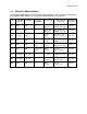
Page 6 of 68 1.4 Electrical Specifications The following table details the IPV electrical specifications. The two-letter version code corresponds to the letters xx in the part number format IPVnnxx-yyy-zzz.
Page 7 of 68 1.5 Environmental Specifications Operating Temperature Range: 0 to 50°C Storage Temperature Range: -40 to 65°C Operating Humidity Range: 0 to 95% RH Non-condensing Storage Humidity Range: 0 to 95% RH Power Usage (Control Circuitry): 55 watts max 1.6 1.6.1 Mechanical Specifications IPV42 Series Width: 2” Depth: 2” Height: 38” (42” with mounting brackets attached) Approximate Shipping Weight: 12 lbs. Chassis: 18 gauge steel, black 1.6.2 IPV70 Series Width: 2” Depth: 2” (3.
Page 8 of 68 1.7 Mounting IPV42 and IPV70 come with SUB-HRDWARE-017 mounting brackets attached. These mounting brackets allow the units to be mounted in the following orientations: IPV units are also compatible with standard tool-less mounting hole patterns. SUBHRDWARE-038 (ordered separately) includes the hardware necessary for this mounting technique.
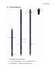
Page 9 of 68 1.8 Physical Features 1. Detachable Mounting Brackets 2. 8, 16, or 24 Receptacles – IEC C13 or NEMA 5-15R 3.
Page 10 of 68 4. Load Current Display – alternates every four seconds to display the current for each outlet section (single-phase units) or phase (three-phase units) 5. Ground – 8-32 chassis nut for ground connection 6. Ethernet RJ45-style Jack (Labeled J25) – use included Ethernet patch cable to connect to a network 7. Ethernet Data LED – blinks orange when Ethernet traffic is present 8. Ethernet Link LED – green when Ethernet connection is good 9.
Page 11 of 68 1.9 Accessories Part Number Description SENSOR-T1-10 Temperature sensor wired to Temperature 1 input. SENSOR-T1H1-10 Same as SENSOR-T1-10, plus a humidity sensor. SENSOR-T2-10 Temperature sensor wired to Temperature 2 input. 060-0907 RJ45 “Y” adapter; allows a “T1” or “T1H1” sensor to be used concurrently with a “T2” sensor. KIT-2556 RJ45 contact sensor breakout kit. Converts RJ45 connector pins 1 to 6 to a terminal strip for easy connection of wires.
Page 12 of 68 2 Getting Started 2.1 Hardware Setup 1. To use the RS232 serial interface, connect the serial cable provided to the port labeled Serial on the top of the unit and connect the other end to a computer DB9 serial port (COM port). 2. To use the web, telnet, or SNMP interfaces, connect a standard Ethernet cable (included) from the RJ45 receptacle labeled NET on the top of the unit to a port on a network switch. 3. Connect the power cable to an appropriate electrical outlet.
Page 13 of 68 Serial channels will use a baud rate of 9600 This board's MAC Address is 00:04:F3:00:21:69 After board is reset, start-up code will wait 5 seconds Default duplex setting for Ethernet connection: Half Duplex The unit is configured for 24 outlets. Resetting system defaults: No Strapping ID: 0 ----------------------------------------------------------------------------FS-FORTH NVRAM Format. START_OF_FREE_NVRAM=0x140 Press any key in 5 seconds to change these settings. Loading Data from NVRAM.
Page 14 of 68 234-56789ABCD- *Unit IP Address: *Subnet Mask: *Default Gateway: MAC Address: *Telnet Access: *Telnet Port: *Web Access: *Secure Server: *Web Port: Ping Enabled: Ping Interval: *Serial Baud Rate: SNMP Menus 192.9.200.201 255.255.255.0 192.9.200.254 00:04:F3:00:06:35 Enabled 23 Enabled Disabled 80 Disabled 60 (minutes) 9600 * - require soft reboot to take effect. -- Other Choices - = Back = Outlet/Environmental status Select Item Number: 6.
Page 15 of 68 3. A home screen will be displayed with a navigation bar on the left and the unit status on the right. Clicking any of the links in the navigation bar will open the corresponding page in the right portion of the screen.
Page 16 of 68 2.3.2 Telnet Interface The telnet interface is text-driven and uses a menu structure almost identical to that accessed via serial connection. Any standard telnet client will work with this interface. Telnet access is enabled by default, but the Admin user can disable it via any interface from the Network Settings configuration screen. Warning: Using the serial and telnet interfaces at the same time may cause unpredictable results. Do not use these interfaces simultaneously. 1.
Page 17 of 68 3 Serial/Telnet Text Interfaces The serial and telnet interfaces use the same text navigation menu to view outlet status and logs, issue outlet commands, and change settings. All of the sections of this navigation menu will be described according to the menu structure. Before using these interfaces, follow the instructions in the Getting Started section to open either a serial or telnet connection to the unit. The serial and telnet interfaces use the same menu structure.
Page 18 of 68 After logging in, the Main Menu should be displayed: Enter UserName: Admin Enter Password: *** Pulizzi IPC3600 Version 2.0.B ------------------------------------Date: mm/dd/yyyy Time: hh:mm Up Time: 0 day(s) 0 hour(s) 0 minute(s) User: Admin Unit Name: Pulizzi IPC3600, Strapping ID: -1234567- 0 Main Menu -Outlet Control Outlet-Environmental Configuration Unit Configuration Outlet-Environmental Status Logout Soft Reboot Choose Strapping Device Select Item Number: 3.
Page 19 of 68 -- Outlet 1 Command Choices -1- Immediate On 2- Immediate Off 3- Reboot -- Other Choices - = Back = Outlet/Environmental status Select Outlet Command: 3 -- Outlet 1 Command Verification -Outlet 1 Requested Command is Reboot. Press the key to implement or the to cancel the command. Notice that the measured voltage, measured current, and calculated real power are displayed at the top of the screen.
Page 20 of 68 Select Item Number: 3.2.1 Outlet Configuration -- Outlet Configuration Sub Menu -- Name Ping IP Link Sequence Reboot ------------------------------------------------------------------------------------------1 Outlet 1 0.0.0.0 http:// 001 Sec 010 Sec 2 Outlet 2 0.0.0.0 http:// 002 Sec 010 Sec 3 Outlet 3 0.0.0.0 http:// 003 Sec 010 Sec 4 Outlet 4 0.0.0.0 http:// 004 Sec 010 Sec 5 Outlet 5 0.0.0.0 http:// 005 Sec 010 Sec 6 Outlet 6 0.0.0.0 http:// 006 Sec 010 Sec 7 Outlet 7 0.0.0.
Page 21 of 68 point before a particular outlet turns on. A Sequence Off command works backwards and first turns off the outlet with the largest Sequence value. Reboot: Integers from 0 to 999 are valid. This setting specifies the number of seconds an outlet remains in the off state following a reboot command. 3.2.
Page 22 of 68 3.2.3 Auto Scheduler -- Auto Scheduler Sub Menu -- Outlet/Group Command Every Day Time ----------------------------------------------------------------1 Outlet 1 Immediate Off Day No Day 20:00 2 Outlet 1 Immediate On Day No Day 06:00 3 4 5 6 7 8 9 A -- Other Choices - = Back = Outlet/Environmental status Select Item Number: The Auto Scheduler may be used to configure outlets or groups of outlets to turn off, turn on, or reboot either daily or weekly.
Page 23 of 68 Select 1 - 7 or press to skip: 1 Press anytime to cancel all. Time format: HH:MM on a 24-hour clock.
Page 24 of 68 6- Display VA Measurements -- Other Choices - = Back = Outlet/Environmental status Select Item Number: 3.2.5.
Page 25 of 68 Control Outlet/Group: If the sensor only needs to be used to report the temperature readings, this setting should be No. If it is set to Yes, this prompt will be followed by an opportunity to select an outlet or group to control. Note: If an outlet or group name is later changed, control from sensors or switches will not work until they are reconfigured with the new name. State: This may be set to either On or Off.
Page 26 of 68 later changed, control from sensors or switches will not work until they are reconfigured with the new name. State: This may be set to either On or Off. If the setting is On, the outlet or group will be turned on whenever the humidity is above the upper threshold or below the lower threshold; the outlet or group will also be turned off when the humidity is between the upper and lower thresholds.
Page 27 of 68 1 VA Monitor Interval Outlet Section Voltage Threshold Current Threshold Ctrl Outlet/Group High Low High Low Outlet/Group Name --------------------------------------------------------------------------------------------2 Outlets (1 - 8) 140 90 20 0 No 3 Outlets (9 - 16) 140 90 20 0 No = Back Select Item Number: Power Log / VA Monitor Interval: Options are 5 minutes, 15 minutes, 60 minutes, or disabled.
Page 28 of 68 Switch 3: Closed Any key to update display = Back This menu option displays the up-to-date temperature, humidity, and contact sensor readings. Sensor measurements are updated every few seconds; press any key to refresh the screen with the latest measurements. 3.2.5.
Page 29 of 68 45678- Time: Date: Timeout in Seconds: Fahrenheit/Celsius: Display: 07:56 03/01/2007 300 Fahrenheit Normal -- Other Choices - = Back = Outlet/Environmental status Select Item Number: Unit Name: Up to 20 characters may be used to name the unit. Admin User Name: Cannot currently be changed from the default “Admin” (case sensitive). Admin Password: The default Admin password is “ipc” (case sensitive).
Page 30 of 68 Note that many of these network settings require a soft reboot to take effect (choose Soft Reboot from the Main Menu). Use DHCP: This option may be either Enabled or Disabled. If DHCP is Enabled, the IP Address, Subnet Mask, and Default Gateway information will be obtained from the network DHCP server, and these obtained values will overwrite whatever settings are in options 2, 3, and 4. If DHCP is Disabled, the values in settings 2, 3, and 4 will be used to communicate on the network.
Page 31 of 68 Ping Interval: May be any integer from 5 to 60 minutes; changes take effect immediately. Serial Baud Rate: May be 9600, 19200, or 38400 baud (default is 9600). Requires a soft reboot to take effect. All other serial settings are fixed at 8 data bits, no parity, 1 stop bit, and no flow control. 3.3.2.
Page 32 of 68 the serial, telnet, or web interfaces three times in a row due to an invalid username or an invalid password. Trap Outlet Activity: This option may be either Enabled or Disabled. When Enabled, a trap will be sent to the Trap IP Address each time an outlet action occurs. Trap System On/Off: This option may be either Enabled or Disabled. When Enabled, a trap will be sent to the Trap IP Address each time the unit completes booting up.
Page 33 of 68 enabled, and the numbers of the outlets to which the user will have access. Here is an example: Select Item Number: 3 Enter New Outlet User Name: Bill Enter password : **** Confirm password: **** Press anytime to cancel all. Outlet User access is currently not defined 1- Outlet User Enabled 2- Outlet User Disabled Select Item Number or press to skip: 1 Outlet Format is 1,2,3 where each location is an outlet.
Page 34 of 68 Select Item Number: The Log Manager contains all settings related to logs and alerts. Logs are kept of the items selected under the Log/Alert Sub Menu and sent by email either on a periodic basis or every time the log is full. Alerts can also be enabled for selected items under the Log/Alert Sub Menu and will be sent immediately after the event occurred. Both logs and alerts can only be sent via email and are not available to be viewed from any of the user interfaces.
Page 35 of 68 -- Other Choices - = Back = Outlet/Environmental status Select Item Number: Events To Log - User Login/Logout: This option may be either Enabled or Disabled. When Enabled, an entry will be added to the log each time a user logs in to or logs out of the serial, telnet, or web interfaces. Events To Log - Failed Login Attempt: This option may be either Enabled or Disabled.
Page 36 of 68 3.3.5 -123- Administrative Utilities Administrative Utilities -Update Firmware Show Firmware version Set System Defaults -- Other Choices - = Back = Outlet/Environmental status Select Item Number: 3.3.5.1 Update Firmware IPV42/IPV70 products feature remotely upgradeable firmware. To upgrade the firmware, select the Update Firmware menu option and respond “y” to the “Continue with reboot and firmware update” prompt.
Page 37 of 68 Press any key in 5 seconds to change these settings. Pulizzi FTP Server ready. At this point the FTP server is ready to receive the firmware upgrade. Using an FTP program (such as FTP Commander), connect to the unit’s IP address (port 21) with the username “Admin” and the Admin password (default is “ipc”), upload the image.bin file, and then disconnect from the unit.
Page 38 of 68 7 8 Outlet 7 Outlet 8 On On -- Other Choices - = Back = Outlet/Environmental status = Next outlet section Select Item Number: Notice that the measured voltage, measured current, and calculated real power are displayed at the top of the screen. For all single-phase units (8-outlet, 16-outlet, and some 24-outlet units), these values correspond to what is measured for the displayed 8outlet section.
Page 39 of 68 4 Web Interface The web interface uses graphical navigation to view outlet status and logs, issue outlet commands, and change settings. All of the sections of this interface will be described according to the menu on the left side of the screen. To open a web connection to an IPV42 or 70, follow the instructions in the Getting Started section of this manual. 4.1 Unit Status The Current Outlet Status screen functions as a Home screen.
Page 40 of 68 Outlet Section Navigation Buttons: The status for one outlet section at a time is displayed on the screen. When connected to a 16- or 24-outlet unit, buttons will be present to switch to each of the additional sections. Hyperlinked Outlet Numbers: Each outlet number can be set up with a hyperlink to a URL. This is a convenient way to store a link to the web-based configuration for a device connected to an outlet. The URL for each outlet can be customized in the Outlet Configuration screen. 4.
Page 41 of 68 4.3 Outlet Control Outlet commands and global commands can be issued from the Outlet Control screen. Outlet Commands: To issue an outlet command, click the combo box for that outlet and choose the desired action – Immediate On, Immediate Off, or Reboot. Pressing the Send Commands button will execute the command. Commands may be issued to multiple outlets at one time.
Page 42 of 68 4.4 Group Control Groups of outlets can be set up in the Group Configuration screen and can be controlled from this Group Control screen. Group Commands: To issue a group command, click the combo box for that group and choose the desired action – Immediate On, Immediate Off, or Reboot. Pressing the Send Commands button will execute the command. Commands may be issued to multiple groups at one time.
Page 43 of 68 4.5 Outlet Configuration Note: To select outlets from an outlet section different than what is shown, first press Save Changes to store the changes on the current screen, then use the outlet section navigation buttons to change to a different section. Changing sections without pressing Save Changes will result in lost data! Outlet Name: Can be a maximum of 20 characters. This setting is used to describe the outlet wherever it appears in the interface.
Page 44 of 68 Sequence: Integers from 0 to 999 are valid (units are seconds). Outlets may be sequenced on or off using Global Sequence On and Global Sequence Off commands. Outlets may also be sequenced on when the unit is powered up by changing the Outlet Startup Mode. Sequencing outlets is primarily used to reduce inrush currents, but it may also be customized using this Sequence setting to allow certain pieces of equipment to entirely boot up before others receive power.
Page 45 of 68 4.6 Group Configuration Name: May be up to 20 characters. Clear this field and press Save Changes to remove the group. Outlet Access: Select the outlets to be included in each group. Note: To select outlets from an outlet section different from what is shown, first press Save Changes to store the changes on the current screen, then use the outlet section navigation buttons to change to a different section.
Page 46 of 68 4.7 Scheduler Configuration The Scheduler screen allows daily or weekly events to be set up for outlets or groups of outlets. Outlet/Group: Type the exact name of an outlet or group, or clear this field and press Save Changes to remove an event. Note: Names are case sensitive! Command: Choose a command – Immediate On, Immediate Off, or Reboot. Day/Week: Outlet commands may be issued Daily or Weekly – choose the appropriate option. Day: If Day/Week is set to Day, this option must be None.
Page 47 of 68 4.8 4.8.1 Environmental Configuration Temperature and Humidity Settings Temperature and humidity probes are accessories that can be purchased from Pulizzi Engineering. Units with “-EP” in the part number have four RJ45-style jacks on the face, one of which is labeled “Temp”. This jack supports two external probes containing a total of up to two temperature sensors and one humidity sensor.
Page 48 of 68 Enabled: A sensor must be enabled before the readings can be displayed. High Threshold: Whenever the readings cross above this threshold, email alerts and/or SNMP traps may be sent, depending on the Log Manager and SNMP Settings configuration. For temperature sensors, the units may be either Fahrenheit or Celsius, depending on what has been selected in the Unit Configuration.
Page 49 of 68 Outlet/Group to ON: This may be set to either Yes or No. If the setting is Yes, the outlet or group will be turned on whenever the contact state is Closed; the outlet or group will also be turned off when the contact state is Open. If the setting is No, the outlet or group will be turned off whenever the contact state is Open; the outlet or group will also be turned on when the contact state is Closed. 4.8.
Page 50 of 68 4.9 Unit Configuration Unit Name: Up to 20 characters may be used to name the unit. Strapping ID: Each unit connected together on a strapping bus must have a unique Strapping ID. The unit with a Strapping ID of ‘0’ is considered the Primary (or master) unit, and those with Strapping IDs of 1 to 23 are considered Secondary (or slave) units. See the Advanced Boot Configuration section for information on changing the Strapping ID.
Page 51 of 68 Unit Day of Week: Select the day of the week that matches the Date. This is important when scheduling events and sending logs. Power Log Interval: Options are 5 minutes, 15 minutes, 60 minutes, or disabled. The Power Log tool multiplies the measured voltage and current together to get the real power and records the calculation at the interval specified by this setting. The Power Log will be disabled if the interval is set to disabled.
Page 52 of 68 4.10 Network Configuration Note that many of the following Network Settings require a soft reboot to take effect (select Soft Reboot from the Unit Configuration screen, then press Save Changes). Use DHCP: This option may be either Enabled or Disabled. If DHCP is Enabled, the IP Address, Subnet Mask, and Default Gateway values will be obtained from the network DHCP server, and these obtained values will overwrite whatever static settings have been entered.
Page 53 of 68 MAC Address: This value is unique to each IPV unit and cannot be changed from this screen. If customization is necessary, see the instructions in the Advanced Boot Configuration section. Serial Baud Rate: May be 9600, 19200, or 38400 baud (default is 9600). Requires a soft reboot to take effect. All other serial settings are fixed at 8 data bits, no parity, 1 stop bit, and no flow control. Telnet Access: This option may be either Enabled or Disabled. Requires a soft reboot to take effect.
Page 54 of 68 Ping Enabled: This option may be either Enabled or Disabled; changes take effect immediately. If Ping is Enabled, the unit individually pings the IP address set up for each outlet (see Outlet Configuration) according to the time specified by the Ping Interval. If there is no ping response, the outlet will be rebooted.
Page 55 of 68 Trap User Login: This option may be either Enabled or Disabled. When Enabled, a trap will be sent to the Trap IP Address each time a user logs in to or logs out of the serial, telnet, or web interfaces. Trap Failed Login: This option may be either Enabled or Disabled. When Enabled, a trap will be sent to the Trap IP Address any time a user tries unsuccessfully to log in to the serial, telnet, or web interfaces three times in a row due to an invalid username or an invalid password.
Page 56 of 68 4.11 User Configuration Up to 11 non-Admin users may be set up with separate user accounts and access rights. These users will be able to log in to the serial, telnet, and web interfaces, but they will see only a subset of the menus available to the Admin user. The menus available will allow the non-Admin user to only view outlet and environmental status and control outlets to which the user has been given access. User Name: May be up to 20 characters.
Page 57 of 68 4.12 Log Configuration Log Configuration contains all settings related to logs and alerts. Logs are kept of the items selected under Events To Log and sent by email either on a periodic basis or every time the log is full. Alerts will also be enabled for the items selected under Alerts To Send and will be sent immediately after the event occurred. Both logs and alerts can only be sent via email and cannot be viewed from any of the user interfaces.
Page 58 of 68 Send Alerts To 2: Up to 30 characters may be used to specify a second email address for all alerts to be sent to. Send Log From: Up to 30 characters may be used to specify the email address that the logs and alerts will be sent from. This will appear as the “From” email address in all sent email messages. Send Log: Options are Daily, Weekly, or When Full. Logs can be sent every day, once a week, or only when the log buffer is full.
Page 59 of 68 Alerts To Send - Power Monitor Threshold: This option may be either Enabled or Disabled. When Enabled, an email alert will be sent each time the measured voltage or current rises above the upper threshold or falls below the lower threshold (as set in the Power Monitor Setup on the Environmental Configuration screen). Alerts To Send - Temperature Threshold: This option may be either Enabled or Disabled.
Page 60 of 68 Strapping is an advanced feature of the IPV42 & IPV70 products. See the Strapping section for more information.
Page 61 of 68 5 SNMP Interface The IPV42/IPV70 SNMP interface conforms to version 2c of the SNMP protocol. To use this interface, the IPV must first have valid network settings and be accessible from one other interface (serial, telnet, or web) for setup purposes. A MIB file for IPV42/IPV70 units should also be downloaded from http://www.pulizzi.com. SNMP is disabled by default.
Page 62 of 68 6 Strapping Strapping is an advanced feature of the IPV42 & IPV70 products. Units with “-EP” in the part number have four RJ45-style jacks on the face, two of which are marked “Strapping”. Up to 24 units may be “strapped” together using lengths of straight-through Ethernet cable (rated Category 5, 5e, or 6) with RJ45 connectors on both ends.
Page 63 of 68 6. Once the connection has been initialized, all of the menu options display the secondary unit’s data. To return to the primary unit, choose Select Strapping Device and enter a Strapping ID of 0.
Page 64 of 68 7 Advanced Boot Configuration IPV42 & 70 units offer advanced configuration options via the serial interface. Follow these steps to access these options: 1. Establish a serial connection to the unit (follow the steps in the Getting Started section). 2. If the unit is connected to a power source, log in and go to the Main Menu, then choose option 6 to do a Soft Reboot. If the unit does not have power, then connect it to a power source. 3. As the unit boots it should display the following text.
Page 65 of 68 Static IP address [192.9.200.201]? Subnet Mask IP address [255.255.255.0]? Gateway address IP address [192.9.200.254]? SECURITY PARAMETERS: Would you like to update the Root Password?[N] HARDWARE PARAMETERS: Set the baud rate of Serial channels[9600]? The new baud rate is 9600 The baud rate will be changed on next power up Please set the baud rate for your terminal accordingly Each development board must have a unique Ethernet MAC address.
Page 66 of 68 Select the Number of Outlets: Select the number of outlets that are present on your IPV42 or IPV70 unit. Strapping ID: This setting is the most important part of configuring strapping. Each unit connected together on a strapping bus must have a unique Strapping ID. The unit with a Strapping ID of ‘0’ is considered the Primary (or master) unit, and those with Strapping IDs of 1 to 23 are considered Secondary (or slave) units.
Page 67 of 68 Appendix A – Contact Sensor Wiring Units with “-EP” in the part number have four RJ45-style jacks on the face, one of which is labeled “Switch”. This jack supports three external contact closures that are sensed as being either open or closed. These inputs may be connected to a mechanical switch or any sensor with an electrically isolated switch output, such as a cabinet door or water sensor.
Page 68 of 68 Appendix B – Recovering From a Lost Password Passwords can only be recovered from the serial interface. Use the following steps to change a lost password: 1. Establish a serial connection to the unit (for more details, follow the steps in the Getting Started section). 2. Restart the unit by disconnecting and reconnecting the power source. A recessed reset switch may be available on some models next to the serial receptacle marked J26 on the end of the unit. 3.