
Installation Manual
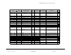
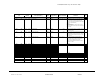
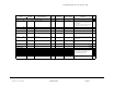
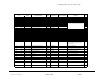
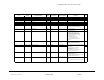
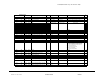
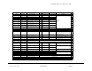
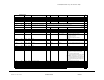
Table Of Contents
- Table of Contents
- 1 Introduction
- 2: Overview and Specifications
- 3 Mechanical Installation
- 4 Electrical Installation
- 5 Communication Installation
- 6 Using the IQ 250/260
- Introduction
- Understanding Meter Face Elements
- Understanding Meter Face Buttons
- Using the Front Panel
- Understanding Startup and Default Displays
- Using the Main Menu
- Using Reset Mode
- Entering a Password
- Using Configuration Mode
- Using Operating Mode
- Understanding the % of Load Bar
- Performing Watt-Hour Accuracy Testing
- 7 Using the I/O Option Cards
- 8 Programming the IQ 250/260
- Overview
- Connecting to the IQ 250/260
- Accessing the IQ 250/260 Device Profile
- Performing Tasks
- Configuring Settings
- Configuring I/O Option Cards
- Polling the IQ 250/260 Meter
- Using the Tools Menu
- Performing Additional Software Tasks
- Appendix A Navigation Maps
- Appendix B Modbus Map
- Appendic C Using DNP Mapping

IQ 250/260 Meter App. B: Modbus Map
www.eaton.com IB02601006E MM-26
Description (Note 1) Format Range (Note 6) Units or Resolution Comments
Modbus Address
Hex Decimal
#
Reg
753B - 753B 30012 - 30012 Reserved Reserved 1
753C - 753C 30013 - 30013 User Settings 2 UINT16 bit-mapped
-------- -------s
s = display secondary volts (1=yes, 0=no) 1
753D - 753D 30014 - 30014 DNP Options UINT16 bit-mapped
-------- ww-i-vvp
p selects primary or secondary values for DNP voltage,
current and power registers
(0=secondary, 1=primary)
vv sets divisor for voltage scaling
(0=1, 1=10, 2=100)
i sets divisor for current scaling
(0=1, 1=10)
ww sets divisor for power scaling in addition to scaling
for Kilo
(0=1, 1=10, 2=100, 3=1000)
Example:
120KV, 500A, 180MW
p=1, vv=2, i=0, and ww=3
voltage reads 1200, current reads 500, watts reads 180
1
753E - 753E 30015 - 30015 User Settings Flags UINT16 bit-mapped
vvkgeinn srpdywfa
vv = number of digits after decimal point for voltage
display.
0 - For voltage range (0 - 9999V)
1 - For voltage range (100.0kV - 999.9 kV)
2 - For voltage range (10.00kV - 99.99 kV)
3 - For voltage range ( 0kV - 9.999 kV)
This setting is used only when k=1.
k = enable fixed scale for voltage display.
(0=autoscale, 1=unit if vv=0 and kV if vv=1,2,3 )
g = enable alternate full scale bar graph current
(1=on, 0=off)
e = enable ct pt compensation
(0=Disabled, 1=Enabled).
i = fixed scale and format current display
0=normal autoscaled current display
1=always show amps with no decimal places
nn = number of phases for voltage & current screen
(3=ABC, 2=AB, 1=A, 0=ABC)
s = scroll (1=on, 0=off)
r = password for reset in use (1=on, 0=off)
p = password for configuration in use (1=on, 0=off)
d = daylight saving time changes (0=off, 1=on)
y = diagnostic events in system log (1=yes, 0=no)
w = power direction
(0=view as load, 1=view as generator)
f = flip power factor sign (1=yes, 0=no)
a
=
apparent power computation method
1
753F - 753F 30016 - 30016 Full Scale Current (for load % bar graph) UINT16 0 to 9999 none If non-zero and user settings bit g is set, this value
replaces CT numerator in the full scale current
calculation. (See Note 12)
1
7540 - 7547 30017 - 30024 Meter Designation ASCII 16 char none 8
7548 - 7548 30025 - 30025 COM1 setup UINT16 bit-mapped
----dddd -0100110
1
7549 - 7549 30026 - 30026 COM2 setup UINT16 bit-mapped
----dddd -ppp-bbb
1
754A - 754A 30027 - 30027 COM2 address UINT16 1 to 247 none 1
754B - 754B 30028 - 30028 Limit #1 Identifier UINT16 0 to 65535 use Modbus address as the identifier (see notes 7, 11,
12)
1
754C - 754C 30029 - 30029 Limit #1 Out High Setpoint SINT16 -200.0 to +200.0 0.1% of full scale Setpoint for the "above" limit (LM1), see notes 11-12. 1
dddd = reply delay (* 50 msec)
ppp = protocol (1-Modbus RTU, 2-Modbus ASCII, 3-
DNP)
bbb = baud rate (1-9600, 2-19200, 4-38400, 6-57600)