
Cut Sheet


Volume 7—Logic Control, Operator Interface and Connectivity Solutions CA08100008E—June 2015 www.eaton.com V7-T1-273
1
1
1
1
1
1
1
1
1
1
1
1
1
1
1
1
1
1
1
1
1
1
1
1
1
1
1
1
1
1
1.9
Pushbuttons and Indicating Lights
30.5 mm Corrosion Resistant Watertight/Oiltight—E34
Selector Switch Selection
Cam and Contact Block Selection
Selector switches in their
varied forms (two-position,
three-position and four-
position) are a big factor
contributing to the great
flexibility of control that a well
rounded line of “pushbuttons”
can achieve. Because of their
flexibility, they tend to cause
difficulty with product
selection and application.
The following systematic
approach should simplify
that task.
Cam and contact block
selection is better understood
if you:
●
Work with each incoming
and outgoing wire/circuit
separately.
●
Recognize the terms NO
and NC only identify the
type of contact by its mode
before mounting to the
operator. The “X-O” chart
(Page V7-T1-275) shows
how that contact will act
after assembly to the
operator with the selected
cam shape. X = closed
circuit, O = open circuit.
●
Up to six NO or NC
contacts may be mounted
behind each plunger
location for a total of
twelve contacts. Single
circuit contact blocks have
only one plunger with the
other side of the block
“open.” Therefore, single
circuit contact blocks
transmit motion to blocks
behind them only for the
position containing the
circuit.
●
Each cam has two
separate lobes, each of
which operates one of the
two contact block plungers
independently of each
other. Those are identified
as position A (locating nib
side) and position B
(opposite of locating nib).
The position designations
give direction in selecting
and mounting of the
contact blocks.
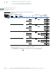
Contact Circuit Locations
Locating Nib
A
B
Systematic Approach
Application: HAND-OFF-
AUTO selector switch. In this
circuit, one incoming line is
distributed to two other
outgoing circuits by the
switch. The two circuits can
be looked at individually.
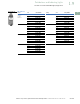
Step 1: Elementary
Diagram.
Construct on paper, or in your
mind, a simple elementary
diagram of the switching
scheme as follows:
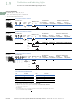
Step 2: “X-O” Pattern.
From the elementary
diagram, you can construct an
“X-O” diagram which
describes when the contacts
are to be closed (X) or open
(O) in the various positions of
the switch. The “X-O” for the
HAND circuit looks like this:
In this circuit, you want a
contact closed on the left
(HAND) but open in the
center and right.
For the AUTO circuit, the
“X-O” diagram would look like
this:
Putting them together, the
complete “X-O” diagram is:
Once the “X-O” diagram has
been generated, the next
step is to select the cam
and contact block, or blocks,
needed to perform the
desired “X-O” functions.
The selection tables on the
following pages list the
various types (shapes) of
cams by number to choose
from and the type of contact
and position to achieve the
function outlined in your
“X-O” diagram.
OFF
HAND
Outgoing
Circuit
AUTO
Outgoing
Circuit
Incoming
Line
HAND OFF AUTO
XOO
HAND OFF AUTO
OOX
X O O
O O X