
Cut Sheet


V7-T1-28 Volume 7—Logic Control, Operator Interface and Connectivity Solutions CA08100008E—June 2015 www.eaton.com
1
1
1
1
1
1
1
1
1
1
1
1
1
1
1
1
1
1
1
1
1
1
1
1
1
1
1
1
1
1
1.3
Pushbuttons and Indicating Lights
Pushbutton Control Stations—Assembled
Technical Data and Specifications
Ratings
Maximum Ampere Ratings for Type N Control Stations
Maximum Ampere Ratings for Type H Control Stations
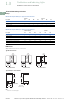
Dimensions
Approximate Dimensions in Inches (mm)
Type N Control Stations
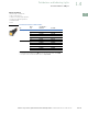
Special Purpose Control Stations
Note
1
2.38 (60.5) for neon indicating light.
Volts AC Volts DC
Description 110 220 440 550 120 240 600
Make and emergency interrupt capacity 30 15 7.5 6 1.0 0.5 0.1
Normal load break 3 1.5 0.75 0.6 1.0 0.5 0.1
Continuous current 10 10 10 10 10 10 10
Description
Volts AC 50/60 Hz Volts DC
120 240 480 600 125 250
Make and emergency interrupt capacity 60 30 15 12 1.1 0.55
Normal load break 6 3 1.5 1.2 1.1 0.55
Continuous amperes 10 10 10 10 10 10
Voltamperes —
Make and emergency interrupt capacity 7200 7200 7200 7200 138 138
Normal load break 720 720 720 720 138 138
3.25
(82.6)
4.00
(101.6)
2.25
(57.2)
a
1.50
(38.1)
2.25
(57.2)
3.25
(82.6)
4.00
(101.6)
2.25
(57.2)
a
1.50
(38.1)
2.25
(57.2)
Single Button Station
5.00
(127.0)
6.00
(152.4)
2.25
(57.2)
a
1.50
(38.1)
2.25
(57.2)
Two Button Station Three Button Station
3.13
(79.5)
0.75 (19.1)
Pipe Tap
2.25
(57.2)
3.38
(85.9)
6.25
(158.8)
5.50
(139.7)
Ship Wt.
2.5 Lb (1.1 kg)