
Cut Sheet


Volume 7—Logic Control, Operator Interface and Connectivity Solutions CA08100008E—June 2015 www.eaton.com V7-T1-345
1
1
1
1
1
1
1
1
1
1
1
1
1
1
1
1
1
1
1
1
1
1
1
1
1
1
1
1
1
1
1.11
Pushbuttons and Indicating Lights
30.5 mm Class I Division 2 Hazardous Locations—10250T/E34
UL (NEMA) Type 3, 3R, 4, 4X, 12, 13, NEC Class I Division 2, Groups B, C and D
●
Four-position maintained
●
Non-illuminated
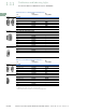
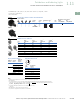
Four-Position Selector Switch—Non-Illuminated
Switch and Color Selection
Key Operated Selection Key Removal Positions
7
Notes
1
Bolded circuit corresponds to “X-O” circuit selection. X = closed circuit, O = open circuit.
2
M = Maintained.
3
To order different type or color selector switch, simply substitute the underlined characters with appropriate suffix code from the
Switch and Color Selection table above. Example: 10250T743LL
. For keyed selector switch, substitute the underlined characters with
T_ (cam) + _ (key removal position). Example: 10250T743T77
.
4
Designed for added ingress protection. For use in maintained operators only.
5
10250T only.
6
M = Maintained. S = Spring return in direction of arrow (
W
).
7
Key removal in “spring return from” positions not recommended.
Operator Position
1
Operator
Action
2
Contact
Type
Cam
Code
Black Knob—Selector Switch
3
Mounting Location
1
10250T
Catalog Number
E34
Catalog Number12
X
O
O
O
O
X
O
O
O
O
X
O
O
O
O
X
1NC
1NO
1NO
1NC
7 10250T743BK
E34EX743BK
Color
Knob
Suffix Code
Lever
Suffix Code
Lever
4
Suffix Code
Coin Slot
5
Suffix Code
Black BK BL BA BC
Red RK RL RA RC
Green GK GL GA GC
Yellow YK YL YA YC
White WK WL WA WC
Gray AK AL AA AC
Blue LK LL LA LC
Orange NK NL NA NC
10250T743_
E34EX743_
M
M
M
M
Knob
Lever
Coin Slot
5
Number of
Position
Operator
Action
6
Suffix and
Removal
Position
2 M M T1 + 1, 2, 3
M
Q
ST1 + 2
3 M M M T3 + 1–7
S
W
M M T3 + 1, 4, 5
S
W
M
Q
ST3 + 4
M
M
Q
S T3 + 2, 4, 6
4 MMMM T7 + 7
Code
Suffix
Key Removal
Position
1 Right only
2 Left only
3 Right and left
4 Center only
6 Left and center
7 All positions
L
C
R