
Cut Sheet


Volume 7—Logic Control, Operator Interface and Connectivity Solutions CA08100008E—July 2015 www.eaton.com V7-T3-9
3
3
3
3
3
3
3
3
3
3
3
3
3
3
3
3
3
3
3
3
3
3
3
3
3
3
3
3
3
3
Volume 7—Logic Control, Operator Interface and Connectivity Solutions CA08100008E—July 2015 www.eaton.com V7-T3-9
3
3
3
3
3
3
3
3
3
3
3
3
3
3
3
3
3
3
3
3
3
3
3
3
3
3
3
3
3
3
3.2
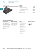
Control Relays and Timers
Ter m i n a l B l o c k R el ay s
Standard DPDT Screw Connection Terminal Block Relays
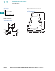
Note
1
The separating plate, XRAPLCESK, should be installed for voltages greater than 250 V (L1, L2, L3) between identical terminal points of adjacent modules.
Potential bridging is then possible with the XRAFBST bridge system.
Catalog Number XRU2D12 XRU2D24 XRU2D24U XRU2D120U
Replacement Relay XRR2D12 XRR2D24 XRR2D24 XRR2D120U
Input voltage 12 Vdc 24 Vdc 24 Vac/Vdc 120 Vac/110 Vdc
Connection Data
Rigid solid AWG (mm
2
) 26–14 (0.14–2.5) 26–14 (0.14–2.5) 26–14 (0.14–2.5) 26–14 (0.14–2.5)
Flexible stranded AWG (mm
2
) 26–14 (0.14–2.5) 26–14 (0.14–2.5) 26–14 (0.14–2.5) 26–14 (0.14–2.5)
Input Data for 1PDT Spring Cage Versions
Input voltage 12 Vdc 24 Vdc 24 Vac/Vdc 120 Vac/110 Vdc
Permissible range See Page V7-T3-10 See Page V7-T3-10 See Page V7-T3-10 See Page V7-T3-10
Typical input current 33 mA 18 mA 17.5 mA 4.5 mA (120 Vac)/4.2 mA (110 Vdc)
Typical response time 8 ms 8 ms 8 ms 7 ms
Typical release time 10 ms 10 ms 10 ms 10 ms
Input protection Polarity protection diode,
free-wheeling diode
Polarity protection diode,
free-wheeling diode
Bridge rectifier Bridge rectifier
Output Data
Contact type 2PDT Single contact, 2PDT Single contact, 2PDT Single contact, 2PDT
Contact material AgNi AgNi AgNi AgNi
Max. switching voltage 250 Vac/Vdc
1
250 Vac/Vdc
1
250 Vac/Vdc
1
250 Vac/Vdc
1
Min. switching voltage 5 V 5 V 5 V 5 V
Limiting continuous current 6 A 6 A 6 A 6 A
Max. inrush current 15 A (300 ms) 15 A (300 ms) 15 A (300 ms) 15 A (300 ms)
Min. switching current 10 mA 10 mA 10 mA 10 mA
Min. switching power 50 mW 50 mW 50 mW 50 mW
General Data
Ambient temp range –4 °F to +140 °F (–20 °C to +60 °C) –4 °F to +140 °F (–20 °C to +60 °C) –4 °F to +140 °F (–20 °C to +60 °C) –4 °F to +140 °F (–20 °C to +60 °C)
Rated operating mode 100% operating factor 100% operating factor 100% operating factor 100% operating factor
Inflammability class V0, in accordance with UL 94 V0, in accordance with UL 94 V0, in accordance with UL 94 V0, in accordance with UL 94
Mechanical service life 3 x 10
7
cycles 3 x 10
7
cycles 3 x 10
7
cycles 3 x 10
7
cycles