
Cut Sheet


V7-T3-106 Volume 7—Logic Control, Operator Interface and Connectivity Solutions CA08100008E—July 2015 www.eaton.com
3
3
3
3
3
3
3
3
3
3
3
3
3
3
3
3
3
3
3
3
3
3
3
3
3
3
3
3
3
3
V7-T3-106 Volume 7—Logic Control, Operator Interface and Connectivity Solutions CA08100008E—July 2015 www.eaton.com
3
3
3
3
3
3
3
3
3
3
3
3
3
3
3
3
3
3
3
3
3
3
3
3
3
3
3
3
3
3
3.4
Control Relays and Timers
General Purpose Plug-In Relays
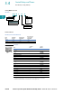
Approximate Dimensions in Inches (mm)
D8PR7TF
D8PR6TE with D8PA5 Bracket Attached
D8PR7TE with D8PA5 Bracket Attached
D8PA1
Note: Minimum spacing around relay = 0.20 inches (5 mm).
Two 0.18 (4.5) Dia. Holes
or M4 Tapped Holes
2.70 (68.5) Max.
1.32 (33.5)
Max.
0.08 (2.0)
1.85
(47.0)
Max.
0.18
(4.5)
0.03
(0.8)
2.36 (60.0)
1.99 (50.5)
Max.
0.25 (6.4)
0.43
(11.0)
0.12
(3.0)
01
24
68
2.362 0.007
(60.0 0.2)
Mounting Holes
(Bottom View)
Terminal Arrangement/
Internal Connections
(Top View)
Two 0.18 (4.5) Dia. Holes
or M4 Tapped Holes
1.32 (33.5)
Max.
0.08 (2.0)
2.09
(53.0)
Max.
0.03
(0.8)
2.07 (52.5) Max.
1.99
(50.5) Max.
0.25 (6.4)
0.43
(11.0)
01
46
1.574 0.003
(40.0 0.1)
Mounting Holes
(Bottom View)
Terminal Arrangement/
Internal Connections
(Top View)
Two 0.18 (4.5) Dia. Holes
or M4 Tapped Holes
1.32 (33.5)
Max
0.08 (2.0)
2.09
(53.0)
Max.
0.03
(0.8)
2.07 (52.5) Max.
1.99
(50.5) Max.
0.25 (6.4)
01
24
68
1.574 0.003
(40.0 0.1)
Mounting Holes
(Bottom View)
Terminal Arrangement/
Internal Connections
(Top View)
0.43
(11.0)
2.19 (55.5)
Max.
2.03
(51.5)
Max.
0.20
(5.0)
1.574 0.003
(40.0 0.1)
1.39 (35.2)
Max.
0.57
(14.5)
1.574 0.003
(40.0 0.1)
Two M4 or
0.18 (4.5) Dia. Holes
Mounting Holes
(Bottom View)