
Cut Sheet


V7-T3-170 Volume 7—Logic Control, Operator Interface and Connectivity Solutions CA08100008E—July 2015 www.eaton.com
3
3
3
3
3
3
3
3
3
3
3
3
3
3
3
3
3
3
3
3
3
3
3
3
3
3
3
3
3
3
3.8
Control Relays and Timers
Ti m i ng Relay s
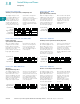
Function #13—Universal TR
ON Delay Control Signal Start, Trailing Edge OFF
The supply voltage U must
be constantly applied to the
device. When the control
switch S is applied, the set
interval t begins. After the
interval t has expired, the
output relay R switches to
the ON position. The relay
will remain in that position
until the control switch
opens. If the control switch is
opened prior to interval t
timing out, the relay will
remain in the OFF position
and any elapsed time will be
erased.
Function #14—Universal TR, TRN, TMR5, TMRP
Flasher, Pause First
Cycle 1 (Power Start, OFF First)
When the supply voltage U
is applied, the set interval t
begins. After the interval t
has expired, the output relay
R switches to the ON
position and set interval t will
begin again. After interval t
has expired, the relay will
switch to the OFF position
for the set interval t. This
cycle will repeat at a 1:1
ratio until supply voltage U
is interrupted.
Function #15—TMR5, TMRP, E5-248
Watchdog
Retriggerable Single Shot
The supply voltage U must
be constantly applied to the
device. When the control
switch S is applied, the relay
switches to the ON position
and the set interval t begins.
After the interval t has
expired, the output relay R
switches to the OFF position.
Closing the control switch
during interval t will reset the
time. Continuous cycling of
the trigger signal at a rate
faster than the preset time
will cause the relay to remain
in the ON position.
Input Power (U)
LED U/t*
Trigger Signal (S)
Output LED**
Output Relay (R)
t<t
Input Power (U)
LED U/t*
Output LED**
Output Relay (R)
t <ttttt
Input Power (U)
Trigger Signal (S)
Output Relay (R)
t<t<tt
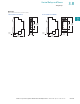
Function #16—TRN, TMRP
Flasher, ON First
Cycle 3 (Power Start, ON First)
When the supply voltage U
is applied, the relay switches
to the ON position and set
interval t begins. After the
interval t has expired, the
output relay R switches to
the OFF position and set
interval t will begin again.
After interval t has expired,
the relay will again switch to
the ON position for the set
interval t. This cycle will
repeat at a 1:1 ratio until
supply voltage U is
interrupted.
Function #17—TRF, E5-248
ON Delay Control Signal Start, Leading Edge OFF
The supply voltage U must
be constantly applied to the
device. When the control
switch S is applied, the set
interval t begins. After the
interval t has expired, the
output relay R switches to
the ON position. The relay
will remain in that position
until the control switch has
opened and closed. If the
control switch is opened and
closed prior to interval t
timing out, the relay will
remain in the OFF position
and any elapsed time will be
erased.
Function #18—TRF, E5-248
Flasher—Control Signal Start, Pause First
The supply voltage U must
be constantly applied to the
device. When the control
switch S is closed, the set
interval t begins. After the
interval t has expired, the
output relay R switches to
the ON position and set
interval t will begin again.
After interval t has expired,
the relay will switch to the
OFF position for the set
interval t. This cycle will
repeat at a 1:1 ratio until
supply voltage U is
interrupted. The control
switch is ignored during
the cycle.
Input Power (U)
Output LED**
Output Relay (R)
t t tt t <tt
Input Power (U)
Trigger Signal
Output LED**
Output Relay (R)
tt
Input Power (U)
Trigger Signal
Output LED**
Output Relay (R)
t t t t <t