
Cut Sheet


Volume 7—Logic Control, Operator Interface and Connectivity Solutions CA08100008E—July 2015 www.eaton.com V7-T3-171
3
3
3
3
3
3
3
3
3
3
3
3
3
3
3
3
3
3
3
3
3
3
3
3
3
3
3
3
3
3
3.8
Control Relays and Timers
Ti m i n g Rel ay s
Function #19—TRF, E5-248
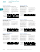
Flasher—Control Signal Start, ON First
The supply voltage U must
be constantly applied to the
device. When the control
switch S is closed, the relay
switches to the ON position
and set interval t begins.
After the interval t has
expired, the output relay R
switches to the OFF position
and set interval t will begin
again. After interval t has
expired, the relay will again
switch to the ON position
for the set interval t. This
cycle will repeat at a 1:1
ratio until supply voltage U
is interrupted. The control
switch is ignored during
the cycle.
Function #20—TRF
Signal ON/OFF Delay
The supply voltage U must
be constantly applied to the
device. When the control
switch S is closed, the relay
switches to the ON position
and set interval t begins.
After the interval t has
expired with the control
switch still closed, the output
relay R switches to the OFF
position. When the control
switch is opened, the relay
will switch to the ON position
again and the interval t will
begin. If the control switch is
closed and opened within the
interval t, the relay will remain
in the ON position until
interval t has timed out after
the control switch is opened.
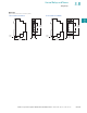
Function #21—TMRP
ON/OFF Delay
Make/Break with Control Switch Trigger
The supply voltage U must
be constantly applied to the
device. When the control
switch S is closed, the set
interval t begins. After the
interval t has expired, the
output relay R switches to
the ON position. When the
control switch is opened,
interval t will begin again.
After interval t has timed out,
the relay will switch to the
OFF position. If supply
voltage U is removed at any
time, the relay will return to
the OFF position.
Input Power (U)
Trigger Signal
Output LED**
Output Relay (R)
<tt t t t
Input Power (U)
Trigger Signal
Output LED**
Output Relay (R)
t t <t t
Input Power (U)
Trigger Signal
Output LED**
Output Relay (R)
tt t
Function #22—TMRP, E5-248
Single Pulse Generator, Voltage Controlled
When the supply voltage U
is applied, the set interval t
begins. After the interval t
has expired, the relay will
switch to the ON position for
0.5 seconds before returning
to the OFF position. Supply
voltage U must be removed
and reapplied to repeat the
pulse.
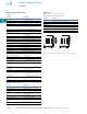
Function #23—N/A
Memory Latch
Control Switch Make
The supply voltage U must
be constantly applied to the
device. Output changes state
with every closure of the
control switch S (leading
edge).
Function #24—TMR6
True OFF Delay
When the supply voltage U
is applied, the relay switches
to the ON position. When
supply power is removed, set
time interval t begins. After
interval t has expired, the
relay switches to the OFF
position and will remain there
until supply power U is
applied again.
Input Power (U)
Output LED**
Output Relay (R)
tt
Input Power (U)
Trigger Signal
Output LED**
Output Relay (R)
Input Power (U)
Output Relay (R)
t