
Cut Sheet


Volume 7—Logic Control, Operator Interface and Connectivity Solutions CA08100008E—February 2014 www.eaton.com V7-T4-77
4
4
4
4
4
4
4
4
4
4
4
4
4
4
4
4
4
4
4
4
4
4
4
4
4
4
4
4
4
4
4.5
PLC, I/O and Communications Products
XI/ON Series Remote I/O
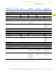
XNE Gateways
XN Gateways with Built-In Supply Module
Description Unit XNE-GWBR-PBDP XNE-GWBR-CANOPEN XNE-GWBR-2ETH-IP
Fieldbus PROFIBUS-DP CANopen Ethernet
Protocol PROFIBUS-DPV0 and PROFIBUS-DPV1 CANopen EtherNet/IP
Maximum number of stations 48 modules (XN, XNE) of slice design or
max. length of station: 1m
62 modules (XN, XNE) of slice design or
max. length of station: 1m
74 modules (XN, XNE) of slice design or
max. length of station: 1m
System supply (U
SYS
) Vdc 24/5 24/5 24/5
Permissible range, 5 Vdc (U
SYS
) Vdc 4.7–5.3 4.7–5.3 4.7–5.3
Permissible range, 24 Vdc (U
SYS
) Vdc 18–30 18–30 18–30
Field voltage (U
L
) Vdc 24 24 24
Permissible range (U
L
) Vdc 18–30 18–30 18–30
Ripple % <5 (to EN 61131-2) <5 (to EN 61131-2) <5 (to EN 61131-2)
Servicing interface PS/2 socket PS/2 socket Mini USB
Fieldbus terminals Push-in spring-cage terminals Push-in spring-cage terminals 2x RJ45 socket
Transfer rate kBit/s 9.6–12,000 20, 50, 125, 250, 500, 800, 1000 10,000, 100,000
Data transfer rate setting Automatic Through DIP switch or automatically Automatic
Address assignment Through DIP switch Through DIP switch Through DIP switch, BootP, DHCP or PGM
Fieldbus termination Through DIP switch Through DIP switch —
Number of parameter bytes 2 — —
Number of diagnosis bytes 2 — —
Address range 1–125 decimal 1–63 decimal 1–254 decimal
Description Unit XN-GWBR-PBDP XN-GWBR-CANOPEN XN-GWBR-DNET XN-GWBR-MODBUS-TCP XN-PLC-CANOPEN
Fieldbus PROFIBUS-DP CANopen DeviceNet Ethernet CANopen
Protocol PROFIBUS-DPV0 CANopen DeviceNet Modbus-TCP CANopen
Maximum number of stations 74 modules (XN, XNE) of
slice design or max. length
of station: 1m
74 modules (XN, XNE) of
slice design or max. length
of station: 1m
74 modules (XN) of slice
design or max. length of
station: 1m
74 modules (XN, XNE) of slice
design or max. length of station:
1m
74 modules (XN, XNE with
limitations) of slice design or
max. length of station: 1m
System supply (U
SYS
) Vdc 24/5 24/5 24/5 24/5 24/5
Permissible range, 5 Vdc (U
SYS
) Vdc 4.7–5.3 4.7–5.3 4.7–5.3 4.7–5.3 4.7–5.3
Permissible range, 24 Vdc (U
SYS
) Vdc 18–30 18–30 18–30 18–30 18–30
Field voltage (U
L
) 24 24 24 24 24
Permissible range (U
L
) Vdc 18–30 18–30 18–30 18–30 18–30
Ripple % <5 (to EN 61131-2) <5 (to EN 61131-2) <5 (to EN 61131-2) <5 (to EN 61131-2) <5 (to EN 61131-2)
Servicing interface PS/2 socket PS/2 socket PS/2 socket PS/2 socket PS/2 socket
Fieldbus terminals 1 x D-sub 9-pin socket Open style connector Open style connector RJ45 bus Open style connector
Transfer rate kBit/s 9.6–12,000 10, 20, 50, 125, 250, 500,
800, 1000
125, 250, 500 10,000, 100,000 10, 20, 50, 125, 250, 500, 800,
1000
Data transfer rate setting — Through DIP switch Through DIP switch Automatic Software
Address assignment 2 decimal rotary coding
switches
2 decimal rotary coding
switches
2 decimal rotary coding
switches
Decimal rotary coding switch,
BootP, DHCP or I/Oassistant
Software
Fieldbus termination External External External — External
Number of parameter bytes 5 — — — —
Number of diagnosis bytes 3 — — — —
Address range 1–99 decimal 1–99 decimal 1–63 decimal 1–254 decimal 1–127 decimal
Program data kByte — — — — 128
Program code kByte — — — — 128
Cycle time for 1k of instructions
(bits, bytes)
ms———— 0.5
Real-time clock — — — — Yes