
Cut Sheet


V7-T4-78 Volume 7—Logic Control, Operator Interface and Connectivity Solutions CA08100008E—February 2014 www.eaton.com
4
4
4
4
4
4
4
4
4
4
4
4
4
4
4
4
4
4
4
4
4
4
4
4
4
4
4
4
4
4
4.5
PLC, I/O and Communications Products
XI/ON Series Remote I/O
Supply Modules
Digital Input Modules
Notes
1
Permissible range for system supply: for U
SYS
= 24 Vdc: 18 to 30 Vdc (to EN 61131-2).
2
Permissible range for field voltage U
L
: to EN 61131-2 (18 to 30 Vdc).
3
Permissible range for rated voltage and field voltage U
L
: to EN 61131-2.
4
The supply terminal (U
L
) provides power for the module electronics and for the sensors at the inputs. The total current required for each module consists of the sum of all partial currents.
5
Part of the XI/ON module’s electronics is supplied with module bus voltage (5 Vdc), the other part through the supply terminal (U
L
).
6
Maximum permissible capacity: 141 nF at 79 Vac/50 Hz; 23 nF at 265 Vac/50 Hz.
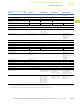
Description Unit XN-BR-24VDC-D XN-PF-24VDC-D XN-PF-120/230VAC-D
Operating voltage 24 Vdc 24 Vdc 120/230 Vac
System supply (U
SYS
) Vdc 24 — —
Permissible range, 24 Vdc (U
SYS
) Vdc 18–30
1
——
Permissible range, 5 Vdc (U
MB
[built into system]
) Vdc 4.7–5.3 — —
Field voltage (U
L
) 24 Vdc 24 Vdc 120/230 Vac
Permissible range (U
L
) 18–30 Vdc 18–30 Vdc
2
102–132 Vac (120 Vac)
195.5–253 Vac (230 Vac)
3
Rated current drawn from module bus (I
MB
)mA —
<
28
<
25
Insulation test (U
i
) Vac 500 500 1500
Ripple % <5 (to EN 61131-2) <5 (to EN 61131-2) <5 (to EN 61131-2)
Maximum operating current (I
L
) A 10 10 10
Maximum system supply current (I
MB
)A 1.5 — —
Number of diagnostic bits 4 4 4
Base module without gateway power supply
Without C connection XN-P3…-SBB/XN-P3…-SBB-B XN-P3…-SBB XN-P3…-SBB
With C connection XN-P4…-SBBC/XN-P4…-SBBC-B XN-P4…-SBBC XN-P4…-SBBC
Description Unit XN-2DI-24VDC-P XN-2DI-24VDC-N XN-2DI-120/230VAC XN-4DI-24VDC-P XN-4DI-24VDC-N
Channels Number 2 2 2 4 4
Rated voltage at supply
terminal (U
L
)
24 Vdc 24 Vdc 120/230 Vac 24 Vdc 24 Vdc
Rated current drawn from
supply terminal (I
L
)
45
mA
<
20
<
20
<
20
<
40
<
40
Rated current drawn from
module bus (I
MB
)
5
mA
<
28
<
28
<
28
<
29
<
28
Insulation test (U
i
) Vac 500 500 1500 500 500
Heat dissipation W 0.7 0.7 1 1 1
Input voltage
Input voltage, rated value 24 Vdc 24 Vdc 120/230 Vac 24 Vdc 24 Vdc
Low level –30V to 5V 30V (U
L
–11V) 0–20 Vac –30V to 5V 30V (U
L
–11V)
High level 11–30V 0–5V 79 Vac–265 Vac
6
15 V–30V 0–5V
Frequency range Hz — — 48–63 — —
Input current
Low level/active level 0 mA–1.5 mA 0 mA–1.7 mA 0 mA–1 mA 0 mA–1.5 mA 0 mA–1.2 mA
High level/active level 2 mA–10 mA 1.8 mA–10 mA 3 mA–10 mA 2 mA–10 mA 1.3 mA–6 mA
Input delay
t
rising edge
µs <200 <200 <20,000 <200 <200
t
falling edge
µs <200 <200 <20,000 <200 <200
Basic modules
Without C connection XN-S3…-SBB 2-conductor proximity switches (Bero
®
)
can be connected, with a permissible quiescent
current of up to 1.5 mA
XN-S3…-SBB XN-S4…-SBBS
XN-S6…-SBBSBB
XN-S4…-SBBS
XN-S6…-SBBSBB
With C connection XN-S4…-SBBC XN-S4…-SBBC XN-S4…-SBBC — —