
Cut Sheet


V7-T4-80 Volume 7—Logic Control, Operator Interface and Connectivity Solutions CA08100008E—February 2014 www.eaton.com
4
4
4
4
4
4
4
4
4
4
4
4
4
4
4
4
4
4
4
4
4
4
4
4
4
4
4
4
4
4
4.5
PLC, I/O and Communications Products
XI/ON Series Remote I/O
Digital Output Modules
Notes
1
The supply terminal (U
L
) provides power for the module electronics and for the consumers at the outputs. The total current required for each module consists of the sum of all partial currents.
2
Part of the XI/ON module’s electronics is supplied with module bus voltage (5 Vdc), the other part through the supply terminal (U
L
).
3
To increase the maximum output current to up to 1A, two outputs can be connected in parallel.
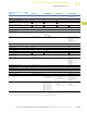
Description Unit XN-2DO-24VDC-0.5A-P XN-2DO-24VDC-0.5A-N XN-2DO-120/230VAC-0.5A XN-2DO-24VDC-2A-P XN-4DO-24VDC-0.5A-P
Channels Number 2 2 2 2 4
Rated voltage at supply terminal (U
L
) 24 Vdc 24 Vdc 120/230 Vac (45–65 Hz) 24 Vdc 24 Vdc
Rated current drawn from supply
terminal (for 0 mA load current) (I
L
)
1
mA
<
20
<
20
<
20
<
50
<
25
Rated current drawn from module
bus (I
MB
)
2
mA
<
32
<
32
<
35
<
33
<
30
Insulation test (U
i
) Vac 500 500 1500 500 500
Heat dissipation W Normally 1 Normally 1 Normally 1 Normally 1 Normally 1
Output voltage
High level >U
L
–1 Vdc <GND
L
+1 Vdc >U
L
–2 Vac,
(zero-point switching triac)
>U
L
–1 Vdc >U
L
–1 Vdc
Output current
High level (rated) A 0.5 0.5 0.5
3
20.5
High level (permissible range) A <0.6 <0.6 0.02–0.5 <2.4 <0.6
Low level mA — — <1.5 — —
Back-up fuse — — 500 mA FF — —
Surge current (I
S
) A — — 8 (1 period at 60 Hz) — —
Number of parallel-switchable
outputs (maximum)
——— —4
Total module current A 1 1 1 4 2
Delay for signal changeover,
resistive load
From Low to High level µs <100 <100 <T/2 +1 ms <100 <250
From High to Low level µs <100 <100 <T/2 +1 ms <100 <250
Load resistance range >48 ohm >48 ohm At 120 Vac:
240 ohm to 6 kohm
At 230 Vac:
460 ohm to 11.5 kohm
<12 ohm >48 ohm
Utilization factor (%) g 100 100 100 (observe derating) 100 100
The following can be connected: Resistive loads/Inductive loads/Lamp loads
Resistive load ohm >48 >48 — >12 >48
Inductive load H <1.2 <1.2 — <1.2 <1.2
Lamp load (R
LL
) W <3 <12 — <6 <6
Switching frequency
For resistive load (f) Hz <5000 (R
LO
<1 kohm) <100 (R
LO
<1 kohm) — <5000 (R
LO
<1 kohm) <1000 (R
LO
<1 kohm)
For inductive load Hz <2 <2 — <2 <2
For lamps Hz <10 <10 — <10 <10
Number of diagnostic bits 2 2 — 2 1
Diagnostics Yes Yes No Yes Yes
Outputs to EN 61131-1 Protected Protected — Protected Short-circuit proof
Retriggering after elimination of short
circuit (I
i
)
Self-acting Self-acting — Self-acting Self-acting
Basic modules
With C connection XN-S3…-SBC
XN-S4…-SBCS
XN-S3…-SBC
XN-S4…-SBCS
XN-S3…-SBC
XN-S4…-SBCS
XN-S3…-SBC
XN-S4…-SBCS
XN-S4…-SBCS
XN-S4…-SBCSBC