
Cut Sheet


Volume 7—Logic Control, Operator Interface and Connectivity Solutions CA08100008E—July 2015 www.eaton.com V7-T7-15
7
7
7
7
7
7
7
7
7
7
7
7
7
7
7
7
7
7
7
7
7
7
7
7
7
7
7
7
7
7
7.1
Industrial Control Transformers
Trans for mers
Technical Data and Specifications
Insulation System and
Temperature Rise
Industry standards classify
insulation systems and rise as
shown below:
Insulation System
Classification
The design life of transformers
having different insulation
systems is the same—the
lower-temperature systems
are designed for the same life
as the higher-temperature
systems.
Series-Multiple Windings
Series-multiple windings
consist of two similar coils in
each winding that can be
connected in series or parallel
(multiple). Transformers with
series-multiple windings are
designated with an “x” or
“/” between the voltage
ratings, such as voltages of
“120/240” or “240 x 480.”
If the series-multiple winding
is designated by an “x,” the
winding can be connected
only for a series or parallel.
With the “/” designation,
a mid-point also becomes
available in addition to the
series or parallel connection.
As an example, a 120 x 240
winding can be connected
for either 120 (parallel) or
240 (series), but a 120/240
winding can be connected for
120 (parallel), 240 (series) or
240 with a 120 mid-point.
For additional information,
please refer to Volume 2,
CA08100003E.
Ambient
+
Winding
Rise
+
Hot
Spot
=
Temp.
Class
40°C 55°C 10°C 105°C
40°C 80°C 30°C 150°C
25°C 135°C 20°C 180°C
40°C 115°C 30°C 185°C
40°C 150°C 30°C 220°C
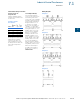
Wiring Diagrams
Diagram 1
Diagram 2
Diagram 3
Diagram 4