
Cut Sheet


Volume 7—Logic Control, Operator Interface and Connectivity Solutions CA08100008E—July 2015 www.eaton.com V7-T7-21
7
7
7
7
7
7
7
7
7
7
7
7
7
7
7
7
7
7
7
7
7
7
7
7
7
7
7
7
7
7
7.1
Industrial Control Transformers
Trans for mers
Accessories
Protection Index IP00
When terminal covers are installed on primary and secondary,
and fuse block covers are used, the protection index is IP20.
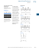
Finger-Safe Terminal Covers (Optional)
●
Fits CE Marked designs 50–750 VA
●
Fits MTE designs 0.25–750 VA
Finger-Safe Terminal Covers
Finger-Safe Primary Fuse Block Covers
●
Fits two-pole primary fuse blocks on MTE designs
Finger-Safe Primary Fuse Block Covers
Secondary Fuse Clip Cover
Secondary Fuse Clip Cover
Technical Data and Specifications
Overload Capability
Short-term overload is designed into transformers as required by
ANSI. Basically, dry-type distribution transformers will deliver
200% nameplate load for one-half hour, 150% load for one hour
and 125% load for four hours without being damaged, provided
that a constant 50% load precedes and follows the overload.
See ANSI C57.96-01.250 for additional limitations.
Continuous overload capacity is not deliberately designed into
a transformer because the design objective is to be within the
allowed winding temperature rise with nameplate loading.
Insulation System and Temperature Rise
Industry standards classify insulation systems and rise as
shown below:
Insulation System Classification
The design life of transformers having different insulation
systems is the same—the lower-temperature systems are
designed for the same life as the higher-temperature systems.
Series-Multiple Windings
Series-multiple windings consist of two similar coils in each
winding that can be connected in series or parallel (multiple).
Transformers with series-multiple windings are designated
with an “x” or “/” between the voltage ratings, such as voltages
of “120/240” or “240 x 480.” If the series-multiple winding is
designated by an “x,” the winding can be connected only
for a series or parallel. With the “/” designation, a mid-point
also becomes available in addition to the series or parallel
connection. As an example, a 120 x 240 winding can be
connected for either 120 (parallel) or 240 (series), but a
120/240 winding can be connected for 120 (parallel),
240 (series) or 240 with a 120 mid-point.
For additional information, please refer to Volume 2,
CA08100003E.
Description Catalog Number
Four terminal transformers FSK4
Four terminal Series 2 transformers only FSK4S2
Six terminal transformers FSK6
Description Catalog Number
Primary fuse block covers FSKFB
Description Catalog Number
Fits 500 VA and smaller models SFCS
Fits models greater than 500 VA SFCL
FSK4
FSK6
FSKFB
Ambient + Winding Rise + Hot Spot = Temp. Class
40°C 55°C 10°C 105°C
40°C 80°C 30°C 150°C
25°C 135°C 20°C 180°C
40°C 115°C 30°C 185°C
40°C 150°C 30°C 220°C