
Cut Sheet


V7-T8-48 Volume 7—Logic Control, Operator Interface and Connectivity Solutions CA08100008E—July 2014 www.eaton.com
8
8
8
8
8
8
8
8
8
8
8
8
8
8
8
8
8
8
8
8
8
8
8
8
8
8
8
8
8
8
8.1
Terminal Blocks, Fuse Blocks and Fuse Holders
IEC—XB Series
Fuse Terminal Blocks
Contents
Description Page
Single Level—Through-Feed . . . . . . . . . . . . . . . . . V7-T8-32
Single Level—Ground Blocks . . . . . . . . . . . . . . . . . V7-T8-37
Multi-Conductor Terminal Blocks . . . . . . . . . . . . . V7-T8-39
Multi-Conductor Ground Blocks . . . . . . . . . . . . . . V7-T8-42
Double Level Blocks . . . . . . . . . . . . . . . . . . . . . . . V7-T8-44
Triple Level Blocks . . . . . . . . . . . . . . . . . . . . . . . . . V7-T8-46
Fuse Terminal Blocks
Accessories . . . . . . . . . . . . . . . . . . . . . . . . . . . V7-T8-49
Technical Data and Specifications . . . . . . . . . . V7-T8-50
Dimensions . . . . . . . . . . . . . . . . . . . . . . . . . . . V7-T8-50
Disconnect and Component Terminal Blocks . . . . V7-T8-51
Hybrid Terminal Blocks . . . . . . . . . . . . . . . . . . . . . V7-T8-54
Mini Spring Cage . . . . . . . . . . . . . . . . . . . . . . . . . . V7-T8-56
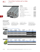
Fuse Terminal Blocks
Product Description
The spring cage fuse terminal
blocks act as a fuse carrier for
5 x 20 mm or 6.3 x 32 mm
fuses. They also allow for
potential distribution with the
double bridge shaft. For
signaling a triggered fuse,
fuse terminal blocks with light
indicators are available (for
both AC and DC voltage).
Product Selection
Spring Cage Connection Fuse Terminal Blocks, for 5 x 20 mm Fuse
Notes
The cartridge fuse holders should be selected according to the maximum power dissipation (self-heating) of the cartridge
fuse inserts. The thermal conditions in closed fuse holes should be checked according to the application and installation.
Higher ambient temperatures are an additional strain on fuse inserts. In applications of this kind, the shift of the rated
current should be taken into consideration accordingly.
Maximum power dissipation at 73.4°F (23°C) (in accordance with IEC 60 947-7-3).
When selecting cartridge fuse inserts, please ensure that the maximum power dissipation specified at right is not exceeded.
Details can be obtained from the fuse suppliers.
Cartridge Fuse Inserts 5 x 20 and 6.3 x 32 mm in accordance. with IEC 60 947-7-3.
1
The current is determined by the fuse used, the voltage by the selected light indicator. See Page V7-T8-49.
Terminal
Width
Maximum
Wire Size
IEC 60 947-7-3
with Fuse
in V/A/AWG
IEC 60 947-7-3
as Disconnect
Terminal Blocks
in V/A/AWG
UL-cUL Ratings
in V/A/AWG Color
Standard
Pack
Catalog
Number
Fuse Terminal Blocks
6.2 mm 10 AWG/4 mm
2
1
/
1
/28–10 250/6.3/28–10 300/6.3/24–10 Black 50 XBPT4FBE
Fuse Terminal Blocks with LED 15–30V, 3.5–8.1A
6.2 mm 10 AWG/4 mm
2
1
/
1
/28–10 250/6.3/28–10 300/6.3/24–10 Black 50 XBPT4FBEL24
Fuse Terminal Blocks with LED 30–60V, 0.8–2.0A
6.2 mm 10 AWG/4 mm
2
1
/
1
/28–10 250/6.3/28–10 300/6.3/24–10 Black 50 XBPT4FBEL60
Fuse Terminal Blocks with LED 110–250V, 0.5–1.0A
6.2 mm 10 AWG/4 mm
2
1
/
1
/28–10 250/6.3/28–10 300/6.3/24–10 Black 50 XBPT4FBEL250
XBPT4FBE