MN04001003E.
MN04001003E.fm Page 2 Tuesday, March 21, 2006 8:26 AM Hazardous High Voltage WARNING Motor control equipment and electronic controllers are connected to hazardous line voltages. When servicing drives and electronic controllers, there may be exposed components with housings or protrusions at or above line potential. Extreme care should be taken to protect against shock. ● Stand on an insulating pad and make it a habit to use only one hand when checking components.
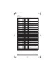
MN04001003E.fm Page 3 Tuesday, March 21, 2006 8:26 AM Users must connect wiring according to the circuit diagram shown below. Please follow all national and state wiring codes when wiring the drive. R/L1 R/L1 U/T1 S/L2 S/L2 V/T2 IM 3-Phase T/L3 T/L3 W/T3 Motor +18V Factory Default Settings Forward/Stop D1 Reverse/Stop D2 Reset D3 Multi-Step 1 D4 4.7 KΩ RA +18V 4.7 KΩ Relay Output Contacts 120V AC/28V DC 3A Factory Default: Fault Indication +18V 4.7 KΩ RC +18V 4.
MN04001003E.fm Page 4 Tuesday, March 21, 2006 8:26 AM Wiring Notes WARNING Ensure that all screws are tightened to the proper torque rating. CAUTION Do not connect the AC input to any of the U/T1, V/T2 or W/T3 terminals as it will damage the drive. Multiple NFX9000 drives can be installed in one location. Please read the following prior to installation: 1. Follow all national and local electrical, construction and safety codes during installation. 2.
MN04001003E.fm Page 5 Tuesday, March 21, 2006 8:26 AM Parameters Parameter Lists Group 0 — User Parameters Code Parameter 0-00 Identity code of drive 1 (read only) Min. 6 Max. Unit Default 1: 40W 2: 100W 3: 200W 4: 400W 5: 750W 6: 1.5 kW Note 0-01 Rated current display — (read only) — 40W: .4A 100W: .8A 200W: 1.6A 400W: 2.5A 750W: 4.2A 1.5 kW: 7.
MN04001003E.fm Page 6 Tuesday, March 21, 2006 8:26 AM Group 2 — Operation Method Parameters Code Parameter Min. Max. Default Note 2-00 Source of frequency command 0 4 0 0: Digital keypad 1: 0 – 10V from AVI 2: 4 – 20 mA from AVI 3: Controlled by V.R.
MN04001003E.fm Page 7 Tuesday, March 21, 2006 8:26 AM Group 4 — Input Function Parameters, continued Code Parameter Default Note 4-05 0, 4 Digital Input 3 (D3) Note: Setting parameter 4-04 to value 3 presets D3 to 3-wire operation Min. 20 6 4-06 Digital Input 4 (D4) 20 7 0: Not used 4: External fault, normally open (NO) 5: External fault, normally closed (NC) 6: Reset 7: Multi-step speed command 1 8: Multi-step speed command 2 9: Jog operation 10: Accel./decel.
MN04001003E.fm Page 8 Tuesday, March 21, 2006 8:26 AM Group 6 — Protection Parameters, continued Code Parameter Min. Max.
MN04001003E.fm Page 9 Tuesday, March 21, 2006 8:26 AM Group 8 — Special Parameters, continued Code Parameter Min. Max. Unit Default Note 8-13 Skip frequency 3 lower bound 0.0 400 Hz 0.0 0.0 – 400 Hz 8-14 Auto restart after fault 0 10 0 0 – 10 8-15 AVR function 0 2 2 0: AVR function enabled 1: AVR function disabled 2: AVR function disabled with deceleration 8-16 Dynamic braking voltage 350 450 V 380 350 – 450V 8-17 DC braking lower bound limit 0.0 400 Hz 0.0 0.
MN04001003E.fm Page 10 Tuesday, March 21, 2006 8:26 AM Common Problems and Solutions, continued Fault Name Fault Description Corrective Action oL2 Motor overload 1. Check settings for parameters 6-03 to 6-05. ocA Over-current during acceleration: 1. Make sure the insulation is adequate at the output line. • Short circuit at motor output 2. Decrease the torque boost setting in parameter 7-02. • Torque boost too high 3. Increase the acceleration time. • Acceleration time too short 4.