
Installation Manual


2 EATON CORPORATION Cutler-Hammer
POW-R-WAY
III
Low Voltage Bus Plug Installation Manual IM017010003E Effective: March 2005
2. Make sure handle is in the OFF position before mounting bus
plug onto busway.
3. Back the screws on the clamp and guide far enough so that
the clamps can be positioned as shown in
Figure 3
and can
clear the flanges of the busway. If installing a bus plug over a
joint cover or if the plug has a 200% neutral, refer to
Figure 4
.
4. Open outlet cover of the plug-in opening on the busway
(Figure 5)
. Do not remove screw from cover. The screw may
be used to close cover later
(Figure 6
).
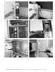
5. Align bus plug with busway. Use the aligning pin mounted on
the end of the bus plug as a reference point.
6. Insert aligning pin into the hole in the busway as shown
in
Figures 7 and 8.
7. Push bus plug onto busway. A reasonable amount of force is
required to ensure that the stabs are engaged onto the bus
bars. To ensure that the bus plug is properly seated, refer to
the arrows in
Figure 9
. The corners of the molded insulators
should be touching all four corners.
8. Position the clamps as shown in
Figure 10
. Make sure that
the clamp is flush against the flange of the busway before
torquing the hardware down. Tighten the hardware until screw
can no longer be turned without doing damage to the treads.
9. Tighten the clamp closest to the guide pin first
(Figure 11)
and
then tighten the clamp on the opposite side
(Figure 12)
of the
bus plug. Continue until all clamps are secure.
10. To ensure that the bus plug is mounted level, check the load
end of the bus plug as indicated in
Figure 12
. The guide
mounted on the back of the bus plug should be touching the
flanges of the busway.
11. To remove, turn the handle to the OFF position. Turn the
power to the busway off. Perform this procedure
(Steps 9 – 3)
in reverse.
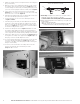
FIGURE 3.
FIGURE 4.
FIGURE 5.
FIGURE 6.
A
A
B
GUIDE
CLAMP
Before assembling plug-in units to busway,
observe the instructions below.
1. When clamp and guide is located on top of a joint cover in
the busway:
(A) Break off tabs "B" for all types of busway.
(B) Break off tabs "A" for busway with 200% (500 TK.) neutral
bars and when tabs interfere with joint cover hardware.
2. When clamp and guide is not located on top of a joint cover
in the busway:
(A) Do not break off tabs "B."
(B) Break off tabs "A" only for busway with 200% (500 TK.)
neutral bar and 50% (1.25 TK.) internal ground bar.