
Cut Sheet


3
Technical Data TD01701001E
Effective March 2017
UL low-voltage busway
Pow-R-Way III
EATON www.eaton.com
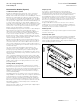
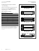
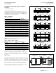
Construction details (Figure 3)
Conductor/insulation system
Bus bars are fabricated from high-strength, 99.9% conductivity
copper or 57% conductivity aluminum. The joint edge of each
busway conductor bar is beveled while the Pow-R-Bridge™ conductor
bars have full rounded edges. This makes for a smooth and easy
connection between the busway and Pow-R-Bridge joint. The phase
and neutral bars are insulated with Class B 130 °C epoxy insulation.
The epoxy powder is applied by an automated fluidized bed process
to ensure uniform thickness. The epoxy powder is applied over the
full length of the preheated bar except for the joint and plug-in contact
surfaces. After the powder has been fused to the bus bar, the bars
enter an oven to cure. This process ensures that all of the epoxy
powder cross links and hardens to the bus bar.
Fluidized bed applied epoxy provides resistance to water absorption
and chemical erosion. Epoxy has outstanding heat transfer
characteristics and is ideally suited for sandwich bus applications.
The uniform thickness and smooth surface provided by epoxy
ensures that the insulation will have no cavities or voids, and also
provides excellent edge coverage to the bars. Epoxy has excellent
dielectric strength, is flame-retardant and resists impacts that other
Class B insulating material could not withstand.
Bus bars for plug-in applications have full-sized welded conductor
tabs at the contact location points of the plug-in outlet. The tabs are
of the same thickness as the conductor bars for all three-wire and
100% neutral configurations. The plug-in conductor tabs extend into
the plug-in outlet, maintaining a true sandwich design throughout the
entire busway length.
The result is improved heat dissipation, better bracing, and
elimination of the need to separate, or flare, the conductor bars
at the plug-in opening. Maintaining a true sandwich design also
eliminates potential pathways for the propagation of flame, smoke,
and gas through the busway housing, commonly referred to as the
“chimney effect.”
Silver- or tin-plating is applied to all joint and contact surfaces after
the fluidized bed epoxy is applied. Aluminum bus bars are plated by
the Alstan
®
88C process. Copper bus bars are plated with a flashing
process. The plating of the conductor tabs provides an extremely
durable contact surface for the spring-loaded connections of bus
plug stab assemblies.
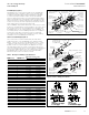
Housing details (see Figure 3)
Pow-R-Way III is constructed with a rugged two-piece extruded
aluminum housing. There are no seams or welds across the top or
bottom sides of the housing. The housing is bolted along the bottom
sides below the bus bars with high tensile strength zinc-plated
hardware. No fastening bolts or screws penetrate the housing or
enter the bus bar package.
Pow-R-Way III achieves the highest 6-cycle short-circuit withstand
ratings available in the industry today. The non-magnetic, all-aluminum
housing provides for excellent heat dissipation and a significant
reduction in reactance and magnetic flux leakage as compared to
a steel or steel and aluminum combination housing. The integrity
and strength of the housing ensures specifiers and users of a safe
and durable installation over a broad spectrum of industrial and
commercial applications.
A protective finish of ANSI 61, epoxy powder paint is applied by an
automated electrostatic process.
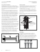
Integral ground
The two-piece, extruded aluminum housing is designed,
manufactured, and UL Listed as a 50% integral ground path
(integral earth) and is fully fault rated. The system ground continuity
is maintained through each joint by the ground path end blocks,
ground path plates, and joint covers. The aluminum joint covers are
furnished with ground path contact surfaces on the inside of each
end. When the covers are installed, the contact surfaces are bolted
directly to the ground path end blocks with four 3/8-16 0.50 inch
(12.7 mm) hex bolts per cover.
A highly visible label is furnished on each joint cover to alert the
installer that the covers must be properly installed to maintain the
ground path. The result is a 50% ground path that ensures ground
continuity with very low resistance characteristics.
Internal ground
Pow-R-Way III offers a 50% ground bus (copper or aluminum) that is
internal to the busway.
Isolated ground option
To meet the growing demand for grounding isolation, Pow-R-Way III
offers a 50% isolated ground bus that is insulated and internal to
the busway. This option is available for application to operations with
heavy microprocessor-based loads or large computer installations
where grounding isolation is essential.
Figure 3. Housing assembly