
Cut Sheet


5
Technical Data TD01701001E
Effective March 2017
UL low-voltage busway
Pow-R-Way III
EATON www.eaton.com
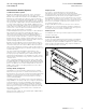
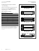
Pow-R-Bridge (Figure 7)
Pow-R-Way III joint connections are made with the Pow-R-Bridge
joint package, which is installed on each section of busway prior
to shipment. A double-headed, torque-indicating bolt is provided
to ensure that proper installation torque is achieved. Fall-away
instruction tags are furnished on the torque-indicating bolt heads to
allow for visual inspection from a distance. When the proper torque
value is achieved, the top bolt head will shear off and allow the tag
to fall to the floor. Any joint that is improperly torqued will retain the
highly visible (caution yellow) tag at the bolt head.
The Pow-R-Bridge can provide an adjustment of ±0.50 inch (12.7 mm)
at each joint. Over adjustment is prevented by the joint covers, which
will only allow a 0.50 inch (12.7 mm) adjustment to be made and
by stopping lances on the conductor bars of the Pow-R-Bridge. The
non-rotating design of the Pow-R-Bridge maintains its configuration
integrity when it has been removed from a section of busway.
The conductors and insulators will not displace or swivel, making
reinstallation of the Pow-R-Bridge quick and easy.
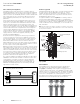
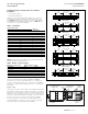
Outdoor Pow-R-Bridge (Figure 8)
Joint connections for outdoor feeder busway are made with a
weatherized version of the Pow-R-Bridge joint. Aluminum water
barriers, 1/16 inch (1.6 mm) thick, are provided across the “T” and
“T opposite” sides of both joint ends on each section of outdoor
busway. Closed cell, neoprene gaskets are applied to the top of
each water barrier and to the inside of the aluminum side access
covers. The aluminum side access covers overlap the top and bottom
access covers and bolt directly onto the end blocks. The outdoor
Pow-R-Bridge has the same ±0.50 inch (12.7 mm) adjustability
and features as the indoor unit and is UL Listed.
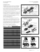
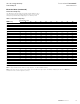
Table 2. Busway Pow-R-Bridge joint dimensions
UL 857
ampere rating
Figure 9
configurations
Dimensions in inches (mm)
W L
Copper
225 A 4.50 (114.3) 7.38 (187.5)
400 A 4.50 (114.3) 7.38 (187.5)
600 A 4.50 (114.3) 7.38 (187.5)
800 A 4.50 (114.3) 7.38 (187.5)
1000 A 5.12 (130.0) 7.38 (187.5)
1200 A 5.62 (142.8) 7.38 (187.5)
1350 A 6.12 (155.4) 7.38 (187.5)
1600 A 7.12 (180.9) 7.38 (187.5)
2000 A 8.38 (212.9) 7.38 (187.5)
2500 B 10.88 (276.4) 7.38 (187.5)
3200 C 15.88 (403.4) 7.38 (187.5)
4000 C 18.38 (466.9) 7.38 (187.5)
5000 D 23.41 (594.6) 7.38 (187.5)
Aluminum
225 A 4.50 (114.3) 7.38 (187.5)
400 A 4.50 (114.3) 7.38 (187.5)
600 A 4.50 (114.3) 7.38 (187.5)
800 A 5.62 (142.8) 7.38 (187.5)
1000 A 6.12 (155.4) 7.38 (187.5)
1200 A 7.12 (180.9) 7.38 (187.5)
1350 A 8.38 (212.9) 7.38 (187.5)
1600 B 9.12 (231.6) 7.38 (187.5)
2000 B 10.88 (276.4) 7.38 (187.5)
2500 C 18.38 (466.9) 7.38 (187.5)
3200 D 19.88 (505.0) 7.38 (187.5)
4000 D 23.41 (594.6) 7.38 (187.5)
Bridge Joint
Pressure Plate
(Top & Bottom)
Double-headed
Torque-Indicating
Bolt (Bottom)
Belleville
Washer
Ground Path Plate
Bridge Joint
Retainer Screw
Ground Path
End Block
130º Epoxy
Insulation
on Bars
.375-16 flg.
Head Hex Bolt
(4 per Cover)
Joint Cover
Ground
Path Label
Captive Nut
Retainer
Ground Path
End Block
High Strength
Glass Polyester
Insulators
Ground
Path Contact
Surface
1/4-20 flg.
Head Hex Bolt
(4 per cover)
Figure 7. Indoor bridge joint features
Figure 8. Outdoor bridge joint features
Figure 9. Pow-R-Bridge joint
DANGER
NOTICE
Ground
Path Contact
Surface
Gasketed
Rear Joint
Cover
Closed Cell
Neoprene Gasket
Water Barrier
Ground Path
End Block
Double-Headed
Joint Torque Bolt
Bridge Joint Retainer Screw
Belleville
Washer
Pressure Plate
(Top & Bottom)
Captive Nut
Retainer
Pow-R-Bridge Joint
Water Barrier
Ground Path
End Block
To rque Bolt
Access Opening
Drain
Hole Plug
Ground
Path Label
Gasketed
Front Joint
Cover
Gasketed Top
Access Cover
Drain
Hole Plug
Gasketed Torque –
Bolt Access Cap
(Top & Bottom)
Gasketed
Cover Plate
Gasketed Bottom
Access Cover
Gasketed
Cover Plate
(L)