
Cut Sheet


7
Technical Data TD01701001E
Effective March 2017
UL low-voltage busway
Pow-R-Way III
EATON www.eaton.com
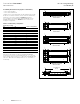
Pow-R-Way III plug-in busway (Figure 11 and Table 4
and Table 5)
•
225 to 5000 A copper
•
225 to 4000 A aluminum
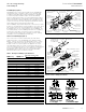
Straight sections of plug-in busway are made only in 24.00 inch
(609.6 mm) incremental lengths with a maximum length of 10 ft
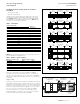
(3 m). Figure 11 depicts the configuration of plug-in busway and
Pow-R-Bridge for the available ampere ratings. See Table 4 below
for reference to the proper configuration.
Table 4. Configuration
UL 857 ampere rating
Figure 10
configurationCu Al
225 225 A
400 400 A
600 600 A
800 — A
1000 — A
1200 800 A
1350 1000 A
1600 1200 A
2000 1350 A
— 1600 B
2500 2000 B
3200 — C
4000 2500 C
— 3200 D
5000 4000 D
Table 5 below illustrates the quantity of plug-in openings per side
that are available per standard section.
Table 5. Number of plug-in openings
Dimensions in inches (mm) Number of plug-in openings
Duct length Front Back
24.00 (609.6) 1 1
48.00 (1219.2) 2 2
72.00 (1828.8) 3 3
96.00 (2438.4) 4 4
120.00 (3048.0) 5 5
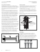
Each section will include one, factory-installed Pow-R-Bridge
mounted to the left end of the busway (with the “T” label to the
top, when viewing the bus from the “F” side). Each Pow-R-Bridge
will have a “T” label that must always match the “T” orientation of
the busway.
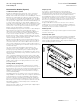
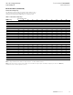
Plug-in outlet
The plug-in outlet and cover are made from a durable, high-strength,
polycarbonate material, which is rated as Class B, 130 °C, insulation.
The plug-in cover is designed to protect the contact surfaces and to
prevent the entry of dirt, dust, or moisture. The cover has a positive
screw close feature that prohibits the opening of the cover without
the use of a tool. The cover is also Utility “leadlock” sealable.
As a countermeasure to the effects of thermal expansion and
mechanical vibration, the plug-in outlet is secured to the busway
housing with high tensile strength locking hardware.
12.00
(304.8)
24.00 Spacing
(609.6)
12.00
(304.8)
Configuration A Top View
1 Bar Per Phase
TT
C
L
C
L
C
L
C
L
TT
12.00
(304.8)
24.00 Spacing
(609.6)
12.00
(304.8)
Configuration B Top View
1 Bar Per Phase
Configuration C Top View
2 Bars Per Phase
Configuration D Top View
2 Bars Per Phase
C
L
C
L
C
L
C
L
12.00
(304.8)
24.00 Spacing
(609.6)
12.00
(304.8)
C
L
C
L
C
L
C
L
12.00
(304.8)
24.00 Spacing
(609.6)
12.00
(304.8)
12.00
(304.8)
24.00 Spacing
(609.6)
12.00
(304.8)
C
L
C
L
C
L
C
L
C
L
C
L
T
T
F
F
Front View
TT
TT
F F
F F
F F
F F
Figure 11. Plug-in busway
Figure 12. Plug-in outlet cover
Cover Can Be Hinged
on Either Side
High Strength
Polycarbonate
Class B 130ºC
Positive
Screw Close
Feature
Fingersafe
Plug-in
Opening
Leadlock
Sealable
Hinge
Pins
A
C
N
B
G