w w w. m g e o p s .
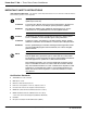
Power-Sure™ 700 — Three Phase Power Conditioners IMPORTANT SAFETY INSTRUCTIONS SAVE THESE INSTRUCTIONS – This manual contains important instructions for Power-Sure™ 700 that must be followed during operation of the equipment. WARNING Opening enclosures expose hazardous voltages. Always refer service to qualified personnel only. ATTENTION L'ouverture des cabinets expose des tensions dangereuses. Assurez-vous toujours que le service ne soit fait que par des personnes qualifiees.
Installation and User Manual WARNING To reduce the risk of fire or electric shock, install in a temperature and humidity controlled indoor area free of conductive contaminants. This equipment is intended only for installations in a RESTRICTED ACCESS LOCATION. ATTENTION Pour réduire le riske d'inccendie ou d'électrocution, installer dans une enciente intérieure contrôlée en température et humidité et sans contaminants conducteurs.
Power-Sure™ 700 — Three Phase Power Conditioners CAUTION: Record All Serial Numbers! RECORD ALL SERIAL NUMBERS FOR THE POWER-SURE™ 700 AND COMPONENTS. THESE SERIAL NUMBERS WILL BE REQUIRED IF YOUR SYSTEM NEEDS SERVICE.
Installation and User Manual Power-Sure™ 700 Three Phase Power Conditioners Installation and User Manual Revision History Power-Sure™ 700 Three Phase Power Conditioners Installation and User Manual Revision: A00 Initial Release 09/2003 A01 ECN#: 003787 02/2004 B00 ECN#: 004681 08/2006 B01 ECN#: 005088 12/2006 86-108814-00 Copyright © 2007 MGE Office Protection Systems All rights reserved. Printed in U.S.A.
Power-Sure™ 700 — Three Phase Power Conditioners (This page left blank intentionally) vi 86-108814-00 B01
Installation and User Manual Contents section description . . . . . . . . . . . . . . . . . . . . . . . . . . . . . . . . . . . . . . . . . . .page IMPORTANT SAFETY INSTRUCTIONS . . . . . . . . . . . . . . . . . . . . . . .ii Certification Standards . . . . . . . . . . . . . . . . . . . . . . . . . . . . . . . . . . . . .ii How to Use This Manual and Symbol Usage . . . . . . . . . . . . . . . . . . .iii CAUTION: Record All Serial Numbers! . . . . . . . . . . . . . . . . . . . . . . . .
Power-Sure™ 700 — Three Phase Power Conditioners Section 3 Maintenance section 3.0 3.1 3.2 3.3 3.4 3.5 3.6 3.7 3.8 3.9 3.10 3.11 3.12 description . . . . . . . . . . . . . . . . . . . . . . . . . . . . . . . . . . . . . . . . . . .page Scope . . . . . . . . . . . . . . . . . . . . . . . . . . . . . . . . . . . . . . . . . . . . . .3 — 1 Preventive Maintenance . . . . . . . . . . . . . . . . . . . . . . . . . . . . . . . .3 — 1 Power-Sure™ 700 Performance Checklist . . . . . . . . . . . . . . . . . .
Installation and User Manual Figures figure description . . . . . . . . . . . . . . . . . . . . . . . . . . . . . . . . . . . . . . . . . . . . . . . . .page 2-1: 2-2: 2-3: 2-4: Power-Sure™ Power-Sure™ Power-Sure™ Power-Sure™ 700 700 700 700 — — — — 10-15kVA Mechanical Cabinet Measurements . . .2 — 2 25-30kVA Mechanical Cabinet Measurements . . .2 — 3 45-150kVA Mechanical Cabinet Measurements . .2 — 4 225-300kVA Mechanical Cabinet Measurements .2 — 5 3-1: 3-2: 3-3: 3-4: 3-5: 3-6: Power Module . . . .
Power-Sure™ 700 — Three Phase Power Conditioners (This page left blank intentionally) c iv 86-108814-00 B01
Installation and User Manual Introduction 1.0 Scope This section is a general description of the Power-Sure™ 700 Three Phase Power Conditioners. Includes receiving, location and storage, electrical, mechanical specifications, monitoring, and internal protection for components. 1.1 Reference Manuals N/A 1.2 Section Descriptions This manual is divided into three sections: Section 1: Introduction This section is a general description of the Power-Sure™ 700 Three Phase Power Conditioners.
Power-Sure™ 700 — Three Phase Power Conditioners 1.3 Receiving and Inspection Notes Before accepting the shipment from the freight carrier, inspect the exterior surfaces of all shipping containers or packaging used, and the equipment, for damage that may have occurred during transit. If the shipping containers or equipment shows evidence of damage, note the damage on the receiving document (bill of lading) prior to signing for receipt of equipment.
Installation and User Manual 1.4.1 Electrical and Performance Specifications *Output Maintained to within ± 3% of nominal. *Input +10% to -20% of the nominal rated input. *Frequency 60 Hertz ± 3 Hertz. Efficiency 95% Minimum. Line Regulation Output is ± 3% of nominal for input variations of +10% to -20% of nominal. Load Regulation Output maintained within 3% from no load to full load. Response Time 1/2 Cycle. Correction Time Output will correct in one step to within ±3% of nominal in 1.
Power-Sure™ 700 — Three Phase Power Conditioners 1.4.3 Input Breaker Main input molded case circuit breaker, rated at 125% of full load input current. 1.5 Monitoring the Power-Sure™ 700 Monitoring of the Power-Sure™ 700 is simple, clean, and effective. Three green light indicators are utilized to display “POWER ON” (output line to neutral for each phase) and one red light indicator to display “ALERT”.
Installation and User Manual Installation and Operation 2.0 Scope This section describes installation requirements, system dimensions, cable connections, and start-up procedures for the Power-Sure™ 700 Three Phase Power Conditioners. WARNING: 2.1 HIGH VOLTAGE, ONLY QUALIFIED ELECTRICIANS SHOULD INSTALL OR PERFORM MAINTENANCE. Installation Notes ◗ The Power-Sure™ 700 requires ventilation. Reference Section 1.3.1 for cabinet placement for each model.
Power-Sure™ 700 — Three Phase Power Conditioners 2.3 Power-Sure™ 700 Installation Drawings and Cabinet Dimensions When sizing the Power-Sure™ 700, be sure to take into consideration all loads and circuits the Power-Sure™ 700 is to supply. Figure 2-1: Power-Sure™ 700 — 10-15kVA Mechanical Cabinet Measurements. 12" (304.
Installation and User Manual Figure 2-2: Power-Sure™ 700 — 25-30kVA Mechanical Cabinet Measurements. 12" (304.8m) FOR INSTALLATION PURPOSES ONLY TO REMOVE TOP: REMOVE RETAINING SCREW IN REAR OF TOP, LIFT REAR AND SLIDE FORWARD 12" (304.8m) FOR INSTALLATION PURPOSES ONLY 24" (609.6m) CLEARANCE FOR SERVICEABILITY ENVIRONMENTAL CLEARNESS TO REMOVE SIDE: REMOVE RETAINING SCREW IN TOP OF PANEL, LIFT PANEL STRAIGHT UP TOP VIEW 21.5" (546.1m) POWER ON 29" (736.
Power-Sure™ 700 — Three Phase Power Conditioners Figure 2-3: Power-Sure™ 700 — 45-150kVA Mechanical Cabinet Measurements. 12.000 FOR INSTALLATION PURPOSES ONLY 24.000 CLEARANCE FOR SERVICEABILITY 12.000 FOR INSTALLATION PURPOSES ONLY ENVIRONMENTAL CLEARNESS TOP VIEW FRONT 45.000 29.000 "ON" LIGHTS OUTPUT "ALERT" LIGHT ALERT A B C CONDITIONED POWER PREFERED INPUT CONDUIT LOCATION PREFERED OUTPUT CONDUIT LOCATION 44.000 5.500 12.
Installation and User Manual Figure 2-4: Power-Sure™ 700 — 225-300kVA Mechanical Cabinet Measurements. 6" CLEARANCE REQUIRED (THIS SIDE) OUTPUT TERMINALS LIFT-OFF ACCESS PANEL OUTPUT ACCESS PLATE LIFT-OFF ACCESS PANEL 1.75" (44.45m) CABINET COOLING FAN EDGE FRAMING FOR SCREENING (18 GAGE .047 THICK STEEL) 1.73" (43.94m) 5" CLEARANCE REQUIRED (THIS SIDE) OUTPUT CONDUIT LOCATION 36" CLEARANCE REQUIRED (THIS SIDE) INPUT CONDUIT LOCATION METAL – LAYER 1 (1.47D X 1.47W , 120 THICK) 1" (25.4m) 4.
Power-Sure™ 700 — Three Phase Power Conditioners As the input voltage (building power) varies, the voltage available at each tap of the transformer will also change. The amount of variation is dependent upon the input sag or surge, turns ratio and transformer losses. By selecting a particular tap voltage, the output can be kept within a tight range. The way in which this is accomplished is that an electronic control card using a micro-processor continually monitors the input voltage.
Installation and User Manual Table 2-1: 480 VAC Input and 208 VAC Output Wire Size Chart.
Power-Sure™ 700 — Three Phase Power Conditioners 2.6 Start-Up Sequence WARNING: THERE ARE DANGEROUSLY HIGH VOLTAGES PRESENT WITHIN THE ENCLOSURE OF THE POWER SUPPLY SYSTEM. CAUTION MUST BE TAKEN WHEN WORKING WITH THE ENCLOSURE. IT IS RECOMMENDED THAT ALL WORK BE PERFORMED BY QUALIFIED ELECTRICAL PERSONNEL ONLY. NOTE: INITIAL START-UP SHOULD BE PERFORMED WITH NO-LOAD ON THE SYSTEM. 2—8 1. Re-install all panels that may have been removed during installation. 2.
Installation and User Manual Maintenance 3.0 Scope This section contains preventive maintenance for the Power-Sure™ 700, electrical connection troubleshooting, checking power modules (SCR), voltage adjustments, and PCB card troubleshooting to assist the user with communication and configuration connections. WARNING: 3.1 HIGH VOLTAGE DANGER OF ELECTRICAL SHOCK, TURN OFF ALL POWER SUPPLING THIS EQUIPMENT PRIOR TO MAINTENANCE. ONLY QUALIFIED ELECTRICIANS SHOULD PERFORM MAINTENANCE OR TROUBLE SHOOTING.
Power-Sure™ 700 — Three Phase Power Conditioners Power-Sure™ 700 Performance Checklist Company: ____________________________________________________________________________________ Model #:_________________________________________Serial #: ______________________________________ 1. Customer Comments or Problems: ______________________________________________________________________________________________ 2. Power Conditioner Environment (clean and dust free): Yes__________ No__________ 3.
Installation and User Manual Power-Sure™ 700 Performance Checklist 9. 10. 11.
Power-Sure™ 700 — Three Phase Power Conditioners 3.2 Troubleshooting Guide SYMPTOM PROBABLE CAUSES 1. No Output on One or More Phases. A. B. C. D. E. Blown Fuse. Defective SCR or Power Module Defective Control Card. Defective Sense Card. No Input. 2. Output is to High or to Low. A. B. C. D. E. Control Card Adjustment. Defective Control Card. Defective Sense Card. Defective SCR or Power Module Input Out of Range. 3. Input Breaker Tripping Off. A. Defective Breaker. B. System Overloaded. C.
Installation and User Manual 3.3.1 Step 1. Disassembling the Power Conditioners 1. Turn off the power to the conditioner at its source. 2. Turn off the input circuit breaker on the unit and the output circuit breakers to all loads. (Remove all loads from unit). 3. Remove the top and side covers to the conditioner. 3.3.2 Step 2. Electrical Connections, Fuses Refer to Sections 3.7 and 3.8 for component locations. 1.
Power-Sure™ 700 — Three Phase Power Conditioners NOTE: When checking the power module assembly, if more than one defective power module is present it will appear as if all the power modules are defective. The individual power module must be isolated from the power transformer: ◗ K1-1 to K2-1 thru K1-7 to K2-7 = High resistance, 1 Meg Ohm. ◗ K1-1 to G1-1 thru K1-7 to G1-7 = 10 to 90 Ohms. ◗ K1-1 to G2-1 thru K1-7 to G2-7 = 1 Meg Ohm. ◗ K2-1 to G2-2 thru K2-7 to G2-7 = 10 to 90 Ohms.
Installation and User Manual RE-CONNECT SEMI-CONDUCTOR FUSE, AND ALL WIRES AND FANS. DOUBLE CHECK THAT ALL CONNECTIONS ARE SECURE. NOTE: Control board #49120 is for 10kVA to 50kVA units. Control board #407415 is for 75kVA and larger. DO NOT CONNECT TB1, TB2, and TB3 CONNECTORS FROM THE CONTROL CARDS #49120/407415 YET! 3.5.1 Check Control Card and Filter Card 1. Verify input to the conditioner matches the units specification. Also verify correct control board #49120 / 407415 jumper setup.
Power-Sure™ 700 — Three Phase Power Conditioners FORMULA AC Input x 2.47 = Volts DC at TP2 480 (Nominal) Example: 475 Volts AC Input x 2.47 = 2.44 Volts DC at TP2 480 (Nominal) 8. After calculations are complete, place DC voltmeter on the 20 volt scale and check between TP2 and TP GND on control card. Adjust pot P1 so meter reads DC level calculated in Step 7 of Section 3.5.1 for all three phases.
Installation and User Manual 3.7 5. Turn the input circuit breaker off. 6. Connect customers equipment. 7. Energize system. 8. Repeat Step #4 and adjust as needed. 9. Be sure over/under detect is connected and if input breaker trips or there is no output voltage, re-calibrate the detect board or replace board if defective. Unit Component Location Diagrams Figure 3-3: Power-Sure™ 700 — 10-15kVA Major Components.
Power-Sure™ 700 — Three Phase Power Conditioners Figure 3-5: Power-Sure™ 700 — 45-150kVA Major Components (Rear View).
Installation and User Manual Figure 3-6: Power-Sure™ 700 — 225-300kVA Cable Connections, Input Output Locations. 6" CLEARANCE REQUIRED (THIS SIDE) OUTPUT TERMINALS OUTPUT ACCESS PLATE LIFT-OFF ACCESS PANEL LIFT-OFF ACCESS PANEL CABINET COOLING FAN EDGE FRAMING FOR SCREENING (18 GAGE .047 THICK STEEL) 5" CLEARANCE REQUIRED (THIS SIDE) OUTPUT CONDUIT LOCATION 36" CLEARANCE REQUIRED (THIS SIDE) 1.75" (44.45m) INPUT CONDUIT LOCATION METAL – LAYER 1 (1.47D X 1.47W , 120 THICK 1.73" (43.94m) 8" (203.
Power-Sure™ 700 — Three Phase Power Conditioners 3.8 SCR Heat Sink Assemblies Figure 3-7: Power-Sure™ 700 — 10-30kVA SCR Heatsink Assembly.
Installation and User Manual Figure 3-8: Power-Sure™ 700 — 45-50kVA SCR Heatsink Assembly.
Power-Sure™ 700 — Three Phase Power Conditioners Figure 3-9: Power-Sure™ 700 — 75-150kVA SCR Heatsink Assembly.
Installation and User Manual Figure 3-10: Power-Sure™ 700 — 225-300kVA SCR Heatsink Assembly. POWER MODULE CABLE TO TRANSFORMER (TYPICAL) GATE LEADS (TYPICAL) FUSIBLE LINK (CONTINUOUS THROUGH EACH POWER MODULE) HEATSINK THERMAL SENSOR INPUT CABLE DIODE 3.9 Field Adjustments of Circuit Cards 3.9.1 Power-Sure™ 700 Control Card #49120/407415 WARNING: 86-108814-00 B01 ALL SERVICE TO THIS PIECE OF EQUIPMENT MUST BY PERFORMED BY QUALIFIED PERSONNEL.
Power-Sure™ 700 — Three Phase Power Conditioners CAUTION: THE CONTROL BOARD (#49120/407415) IS ELECTRICALLY REFERENCED TO HIGH VOLTAGE, NOT EARTH OR CHASSIS GROUND. EXTREME CARE MUST BE USED WHEN TAKING MEASUREMENTS ON THE CONTROL BOARD. ANY AC POWERED INSTRUMENTS MUST BE GROUND ISOLATED PRIOR TO TAKING MEASUREMENTS. A GROUND ISOLATED INSTRUMENT CASE WILL BE AT THE HIGH VOLTAGE LINE POTENTIAL. 3.9.2 Control Card Adjustment Procedure 1.
Installation and User Manual FORMULA X AC Input x 2.47 480 (Nominal) 7. = Volts DC at TP2 Example: 475 Volts AC Input x 2.47 = 2.44 Volts DC at TP2 480 (Nominal) NOTE: Be sure AC input is stable when making this adjustment. If the input changes, you must re-calculate. After calculations are complete, place DC voltmeter on 20 volt scale and check between TP2 and TP GND on control card. Adjust pot P1 so meter reads DC level calculated in Step 6 for all 3 phases.
Power-Sure™ 700 — Three Phase Power Conditioners 2. P1 will adjust the overvoltage set point. One turn on P1 will change the voltage level approximately 1 volt. Clockwise = Decrease Sensitivity. Counter-clockwise = Increase Sensitivity. 3.9.3.3 Delay Adjustment 1. The delay adjustment can be adjusted for a minimum of 5 cycles to a maximum of 15 seconds. The standard set point is 6 seconds. 2. P3 adjusts the delay. ◗ All the way counter-clockwise = 5 cycles. ◗ All the way clockwise = 15 seconds.
Installation and User Manual 3.11 Replacement Parts Individual components are available upon request. Please contact MGE Office Protection Systems for specific part numbers and prices. See Section 3.7 in this manual for component location and description. When contacting MGE Office Protection Systems Service at (949) 268-2800, please have the unit’s full model number and serial number for identification. 3.12 Part Numbers Table 3-1: Power-Sure™ 700 Power Conditioners Part Numbers.
Power-Sure™ 700 — Three Phase Power Conditioners Table 3-1: Power-Sure™ 700 Power Conditioners Part Numbers (Continued).
MODEL NUMBER 200?C. 180?F. 180?F. 10(A) 73(A) 180?F. 9 REFERANCE SPEC. TAG FOR PROPER KVA & VOLTAGE'S TDL-010K-6 TCL-010K-6 TBL-010K-6 TRANS. OVERTEMP. 10(A) SCR OVERTEMP. RL1 5 M M 2 1 2 6 4 5 10(A) 7 (A) 7 (A) 34(A) 32(A) 33(A) 56(A) 10 RL1 6 1 2 208VAC 240VAC 480VAC 8CLX-10K-7A 8DLX-10K-7A REV. 3 TB-3 INPUT VOLTAGE 8BLX-10K-7A BLACK/WHITE TWIST 18 GAGE (TYP.
86-108814-00 B01 47 (A) TRANS. OVERTEMP. SCR OVERTEMP. 40 (A) 480V 5 1 H4 H3 H2 RL1 3 200ºC. 180ºF. 180ºF. 180ºF. 9 TD1 X2 7 73 (A) 120V TD1 2 13 M R "ALERT" RL1 14 80 (A) COOLING FANS (7) IN PARALLEL CONTROL TRANSFORMER 250VA 48 (A) 47 (A) 73 (A) 3 REV. 8DNX-150K-7A TDN-150K-6 480VAC 480VAC 480VAC 8DNX-75K-7A 8DNX-125K-7A TDN-075K-6 TDN-125K-6 INPUT VOLTAGE REFERANCE SPEC.
40 (A) 47 (A) TRANS. OVERTEMP. SCR OVERTEMP. 480V 39 (A) 5 1 RL1 3 X1 7 TD1 73 (A) X2 120V 18 17 16 15 14 13 12 11 10 9 8 7 6 5 4 3 2 1 200ºC. 180ºF. 180ºF. 180ºF.
Power-Sure™ 700 — Three Phase Power Conditioners (This page left blank intentionally) A —4 86-108814-00 B01
MGE Office Protection Systems Customer Care Center Technical Support and Product Services ? Technical questions? If you encounter a problem while following the instructions in this manual, or have questions about the operation, repair, or servicing of your equipment, please visit our web site www.mgeops.com for complete service information.
w w w. m g e o p s . c o m Contact MGE Office Protection Systems United States MGE Office Protection Systems 13 Whatney, Suite #101 Irvine, CA 92618 (949) 268-2800 www.mgeops.com 1 3 W h a t n e y, S u i t e # 1 0 1 , I r v i n e , C a l i f o r n i a 9 2 6 1 8 • w w w. m g e o p s .