Power Management Systems & Products 2.0-1 February 2009 Power Management Systems & Products Sheet 02 001 CA08104001E Contents Power Management Systems & Products Overview Power Xpert Architecture Introduction . . . . . . . . . . . . . . . . . . . . . . . . Power Xpert Meters Power Xpert Meters . . . . . . . . . . . . . . . . . . . . . . . . . . . . . . . . . . . . . . . . Ethernet-Ready Power Quality & Energy (PQ&E) . . . . . . . . . . . . . . . .
.0-2 Power Management Systems & Products February 2009 Sheet 02 002 i ii 1 2 3 4 5 Contents (Continued) Specifications See Eaton’s Cutler-Hammer Product Specification Guide on enclosed CD-ROM: CSI Format . . . . . . . . . . . . . . . . . . . . . . 1995 2004 Section 16901 Section 26 27 13.11 & & 16911 Section 26 09 13.13 Addressable Relay II . . . . . . . . . . . Section 16902, Section 26 29 05, Paragraph 2.02.C Paragraph 2.02.C Analog Input Module . . . . . . . . . . . Section 16901, Section 26 27 13.
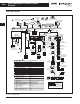
Power Management Systems & Products Overview February 2009 2.0-3 Sheet 02 003 Power Xpert Architecture Introduction Enabling Power System Management Eaton’s Power Xpert Architecture (PXA) provides a complete hardware/ software solution to manage your entire power system. Power Xpert Architecture consists of Power Xpert Meters, Gateways, Switches and Software.
2.
February 2009 Power Management Systems & Products Overview 2.0-5 Sheet 02 005 Power Xpert System — Notes a. Simple Mail Transfer Protocol (SMTP) — Device events and periodic data log file attachments are sent to users in the form of an email from the following Power Xpert products: Power Xpert Foreseer Class Software, Power Xpert Server Core Software, Power Xpert Meters 4000/6000/8000, Power Xpert Gateway 600 and Power Xpert Gateway Cards 1000/2000 Series. b.
2.0-6 Power Management Systems & Products February 2009 Sheet 02 006 i ii 1 2 3 4 5 6 7 8 9 o. Single-port Device Server — Is a device that is used to add network connectivity to a single serial device. These device servers offer a single RS-232/485 serial port to connect a variety of serial devices including meter devices, UPS, PDU, Static Switch, Automatic Transfer Switch, generators, Computer Room Air Conditioners, and other commercial, industrial or business automation equipment.
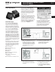
February 2009 Power Management Systems & Products Power Xpert Meters 2.1-1 Sheet 02007 Power Xpert Meters Power Xpert Meters Power Xpert Meter and Display General Description The Power Xpert 4000/6000/8000 Graphic Display uses a simple “twist and click” navigation control dial to easily navigate the menus and drill down into increasing levels of important detail. A “back” key enhances the browser like navigation of the graphic display.
Power Management Systems & Products Power Xpert Meters 2.1-2 February 2009 Sheet 02 008 Ethernet-Ready Power Quality & Energy (PQ&E) i ii Ethernet-Ready Power Quality & Energy (PQ&E) — Power Xpert Meters Layout Diagrams Modbus Master General Description 1 2 One or more Ethernet-ready PQ&E Power Xpert Meters may be deployed in various power distribution and motor control applications.
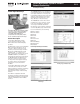
Power Management Systems & Products Network Connectivity February 2009 2.2-1 Sheet 02 009 Power Xpert Gateways Power Xpert Gateways The PXG600 allows you to enable preselected parameters to be trended for each supported device. Selecting the trend symbol will generate a real-time graph for that parameter and can be viewed for the past 24 hours, seven days, 30 days or all past history. i ii 1 The PXG600 also offers direct email notifications to up to 10 users.
2.2-2 Power Management Systems & Products Network Connectivity February 2009 Sheet 02 010 Power Xpert Gateways i ii 1 2 3 4 5 6 7 8 Table 2.2-1. Features of the Power Xpert Gateway 400 vs.
Power Management Systems & Products Network Connectivity February 2009 2.2-3 Sheet 02 011 Connectivity Matrix Table 2.2-2.
Power Management Systems & Products Network Connectivity 2.2-4 February 2009 Sheet 02 012 Connectivity Matrix i Table 2.2-2.
Power Management Systems & Products Network Connectivity February 2009 2.2-5 Sheet 02 013 Product Selection The table below represents many of the parameters displayed on the Web page for a given device, however it is not exhaustive. For the complete list of parameters display, per device, refer to the Device Data Map file at HYPERLINK http://www.eaton.com/powerxpert www.eaton.com/powerxpert. i Table 2.2-3.
2.2-6 Power Management Systems & Products Network Connectivity February 2009 Sheet 02 014 Product Selection i Table 2.2-3.
Power Management Systems & Products Network Connectivity February 2009 2.2-7 Sheet 02 015 Dimensions Power Xpert Gateway — Dimensions in Inches (mm) 10.75 (273.1) 0.18 (6) (4.6) ii 10.25 (260.4) O IN 1 C O M re se t 1 C D V M O C M 24 1.12 (28.4) 1 PXG 400 C 1.99 (50.5) i 0.56 (14.2) 0.24 (6.1) IN M O 0.25 (6.4) 8.75 (222.3) 4 Figure 2.2-3. Power Xpert Gateway 400/600 with Standard Panel Mounting (Brackets Included) 5 11.30 (287.0) 0.25 (6.35) 6 10.80 (274.3) ø0.
Power Management Systems & Products Network Connectivity 2.
Power Management Systems & Products Network Connectivity February 2009 2.2-9 Sheet 02 017 Wiring Guidelines General Wiring Guidelines — RS-485 Network Rule 5: Cable Shielding Table 2.2-5. RS-485 Wiring Guide — Three Terminal Devices The cable shielding and outer jacket should not be stripped back beyond 1-1/2 inches. 3-pole terminal blocks are used to ensure a continuous metallic shield ground path.
2.2-10 Power Management Systems & Products Network Connectivity February 2009 Sheet 02 018 Wiring Guidelines i ii 1 2 3 4 5 INCOM Network INCOM was specifically designed with the intention of delivering a comprehensive and powerful energy management solution for use in electrical distribution environments while ensuring affordability, flexibility, simplicity and noise immunity. An INCOM network installed per the following rules will allow the user to fully realize all of the above advantages.
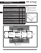
Power Management Systems & Products Network Connectivity February 2009 2.2-11 Sheet 02 019 Wiring Guidelines INCOM Master Device 1 i Main Run Device 10 Device 5 Device 2 ii EOLTR EOLTR Device 3 Note: Device 1 may be a PC with internal CONI Card, a SubNetwork Master (BIM, LDISP), an INCOM MINT (RS-232 MINTII, Ethernet MINT, Modbus RS-485 MINT), an INCOM Gateway (NetLink, Power Xpert Gateway). 2 Tap Tap Device 6 1 Device 8 Device 9 3 4 Device 4 Device 7 Figure 2.2-5.
2.2-12 Power Management Systems & Products Network Connectivity February 2009 Sheet 02 020 IQ Meters i ii Ethernet-Enabled Power Quality & Energy (PQ&E) — IQ Meters Note: The total device count on a PXG600 cannot exceed 96 devices.
Power Management Systems & Products Network Connectivity February 2009 2.
2.
February 2009 Power Management Systems & Products Network Connectivity 2.2-15 Sheet 02 023 IPONI Communication Modules IPONI Communication Modules Metered Parameters/ Communications An IPONI enables communication of the metered parameters and set points consistent with those of the device to which it is attached. Communications Supported Devices The IPONI enables communications over a twisted shielded pair INCOM device network.
2.
February 2009 Power Management Systems & Products Network Connectivity 2.2-17 Sheet 02 025 Power Management Systems Central Energy Display (CED) Power Management Systems Central Energy Display (CED) Communications Non-Volatile Memory Communications between the IQ CED II and IQ Energy Sentinels is accomplished over a twisted pair of conductors on the highly reliable INCOM local area network. A subset of information equivalent to the IQ Energy Sentinel is displayed from power sentinels.
2.2-18 Power Management Systems & Products Network Connectivity February 2009 Sheet 02 026 Power Management Systems Central Energy Display (CED) i Application Description Specifications 5.38 Applications ii ■ ■ 1 ■ ■ 2 3 4 ■ The following are displayed on the membrane NEMA 3R, 12 faceplate: ■ ■ ■ ■ 6 7 ■ 8 9 10 ■ 8.90 ■ 6.68 ■ 9.38 ■ Displayed Parameters ■ 5 Display for up to 50 IQ Energy Sentinel and IQ Power Sentinels. Peak demand alarms. Watt-hour pulse initiator.
Power Management Systems & Products Network Connectivity February 2009 2.2-19 Sheet 02 027 Digital Input Module (DIM) I/O Devices Digital Input Module (DIM) Physical Characteristics Frequency Range ■ ■ ■ ■ ■ ■ Height: 4.25 inches (107.9 mm) Width: 3.54 inches (89.9 mm) Depth: 3.50 inches (88.
2.2-20 Power Management Systems & Products Network Connectivity February 2009 Sheet 02 028 Addressable Relay II i Addressable Relay II ii 1 2 11 12 13 15 16 17 18 19 20 21 ■ Built-in INCOM communications for monitoring in a Power Management Software system. Physical Characteristics ■ Height: 3 inches (76.2 mm) Width: 1.75 inches (44.5 mm) ■ Depth: 4 inches (101.
February 2009 Power Management Systems & Products Power Xpert Systems and Network System Expansion 2.3-1 Sheet 02 029 Power Xpert Ethernet Switches Power Xpert Ethernet Switches Technical Specifications i Table 2.3-1.
Power Management Systems & Products Power Xpert Systems and Network System Expansion 2.3-2 February 2009 Sheet 02 030 Application Information i ii 1 Copper Ethernet Cable Wiring Guidelines The following information can be used as a guide when designing an Ethernet system using Copper Ethernet Cable.
Power Management Systems & Products Power Xpert Systems and Network System Expansion February 2009 2.3-3 Sheet 02 031 Application Information Conventional electrical data signals are converted into a modulated light beam, introduced into the fiber and transported via a very small diameter glass or plastic fiber to a receiver that converts the light back into electrical signals.
2.3-4 Power Management Systems & Products February 2009 Sheet 02032 i This page intentionally left blank. ii 1 2 3 4 5 6 7 8 9 10 11 12 13 14 15 16 17 18 19 20 21 For more information visit: www.eaton.
Power Management Systems & Products Powerware X-SLOT Connectivity Options February 2009 2.
Power Management Systems & Products Powerware X-SLOT Connectivity Options 2.4-2 February 2009 Sheet 02 034 Technical Specifications i ii Technical Specifications Table 2.4-1.
Power Management Systems & Products Powerware X-SLOT Connectivity Options February 2009 2.
Power Management Systems & Products Powerware X-SLOT Connectivity Options 2.4-4 February 2009 Sheet 02 036 Technical Specifications i ii Technical Specifications Table 2.4-2.
Power Management Systems & Products Power Xpert Monitoring Software February 2009 2.5-1 Sheet 02 037 Server Core Power Xpert Software Server Core General Description Power Xpert Software, Server Core Class (Server Core) is the fusion of key components of our PowerNet and Powerware’s PowerVision Software into a single power monitoring package which includes ease of interconnectivity to a wide range of Eaton and third-party communicating devices.
2.5-2 Power Management Systems & Products Power Xpert Monitoring Software February 2009 Sheet 02 038 Server Core i ii 1 2 3 4 5 6 7 8 9 10 11 12 13 Problem Avoidance and Troubleshooting Server Core is Standard With the Functionality of PowerNet Operators receive alerts to potential problems before they occur, such as a breaker timing out to trip. Loads can be shed or switched to alternate sources to prevent critical upstream breakers from unnecessarily tripping on an overload condition.
Power Management Systems & Products Power Xpert Monitoring Software February 2009 2.5-3 Sheet 02 039 Server Core Server Core Optional Modules/Hardware Quality Manager When used in conjunction with Eaton's IQ metering products, lets you see the critical quality attributes for your power system, such as voltage, power, current, transients, harmonics, waveforms and time via a waveform viewer. ■ Spot trends faster with easy-to-read graphical displays of real-time information.
Power Management Systems & Products Power Xpert Monitoring Software 2.5-4 February 2009 Sheet 02 040 Server Core i Ethernet NetLink The NetLink translates INCOM Frequency Shift Key (FSK) to standard Ethernet TCP/IP messages or Modbus RTU or to both. ii The Ethernet NetLink allows connection of 200 meters and protective relays to an Ethernet Network. Configuration can be done remotely and is stored in non-volatile RAM. The NetLink can be applied on dedicated or shared facility Ethernet Networks.
Power Management Systems & Products Power Xpert Monitoring Software February 2009 2.5-5 Sheet 02 041 Server Core Mounting Information Catalog Information The most common location for the NetLink is in a wall-mounted enclosure near a patch panel, a network hub, or a wall-mounted network port. Modbus NetLinks should be mounted in close proximity to the Modbus Master.
Power Management Systems & Products Power Xpert Monitoring Software 2.5-6 February 2009 Sheet 02 042 Server Core Server Core Hardware/ Software Requirements i 120/240 Vac Duplex Receptacle ii Serial Modbus Port 2 Communication 1 1 Hardware Requirements Recommended hardware: ■ ■ INCOM Device Network RJ11 ■ ■ RJ11 3 ■ ■ RJ45 4 Processor type: Dual core or higher. Processor speed: 2.8 GHz or higher. Memory (RAM): 4 GB or more. Disk space: 15 GB available.
Power Management Systems & Products Power Xpert Monitoring Software February 2009 2.5-7 Sheet 02 043 Ethernet-Enabled Software Monitoring Ethernet-Enabled Software Monitoring of IT and Facility Power Equipment Using a single Web server connecting to an Ethernet switch, PXS Server Core will communicate directly with Power Xpert devices (i.e., PX Meters, PX Gateways, and PX Gateway Cards), as well as those third-party devices communicating via SNMP or Modbus TCP and an existing PowerNet system server.
Power Management Systems & Products Power Xpert Monitoring Software 2.
Power Management Systems & Products Power Xpert Monitoring Software February 2009 2.5-9 Sheet 02 045 Foreseer Class Hardware Options To further expand the reach of Power Xpert Software, Foreseer Class, two hardware devices are offered. Data Acquisition Engine (DAE) i ii The Foreseer Data Acquisition Engine is designed specifically for geographically or physically removed Foreseer Class sites where local IT expertise may not exist.
2.
Power Management Systems & Products Power Xpert Monitoring Software February 2009 2.5-11 Sheet 02 047 Power Xpert Software — Foreseer Class Power Xpert Software — Foreseer Class Follow the easy step of consulting with Eaton’s Software & Engineering Services Hotline: 1-800-356-3292 for a quotation of a Foreseer system to support your data center and facility monitoring requirements. Choose the correct base software package to meet your customer’s needs.
2.5-12 Power Management Systems & Products February 2009 Sheet 02048 i This page intentionally left blank. ii 1 2 3 4 5 6 7 8 9 10 11 12 13 14 15 16 17 18 19 20 21 For more information visit: www.eaton.
February 2009 Power Management Systems & Products for Third-Party Integration 2.6-1 Sheet 02 049 PONI Communication Modules Power Xpert Gateway 400/600 The MPONI comes with mounting hardware and attaches to the back of its associated device. MP-4000. The DPONI is powered both by the host product to which it is attached and by the DeviceNet network. Note: Please see IL for detailed register support information for each supported product.
Power Management Systems & Products for Third-Party Integration 2.6-2 February 2009 Sheet 02 050 mMINT i ■ mMINT ■ ii ■ 1 ■ 2 ■ Module Mounting 3 When mounting the mMINT, verify that an 11 mm H x 28 mm W DIN rail is used and that it is within an enclosed space.
Power Management Systems & Products for Third-Party Integration February 2009 2.6-3 Sheet 02 051 Ethernet/Modbus NetLink Modbus NetLink Metered/Monitored Parameters Mounting Information Provides remote access over Ethernet or Modbus to the protective and monitoring parameters of any supported communicating Cutler-Hammer meter, protective relay, breaker or motor starter.
2.6-4 Power Management Systems & Products February 2009 Sheet 02052 i This page intentionally left blank. ii 1 2 3 4 5 6 7 8 9 10 11 12 13 14 15 16 17 18 19 20 21 For more information visit: www.eaton.