
System information


CA08104001E For more information visit: www.eaton.com
2.2-19
February 2009
Power Management Systems & Products
i
ii
1
2
3
4
5
6
7
8
9
10
11
12
13
14
15
16
17
18
19
20
21
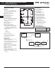
Sheet 02
Network Connectivity
Digital Input Module (DIM)
027
I/O Devices Digital Input
Module (DIM)
Digital Input Module (DIM)
General Description
Eaton’s Cutler-Hammer Digital Input
Module is a device that inter-faces with
up to four standard utility (electric,
gas, water) meters or monitors eight
digital inputs. It translates KYZ pulses
from meters into a register count that
is maintained and compiled within the
DIM module in non-volatile memory.
The pulse count can be accessed from
the DIM module remotely using Cutler-
Hammer Power Management Software
including the Energy Billing application.
The DIM can also be used to
monitor eight digital inputs from
switch closures.
Application Description
■ Reads four separate KYZ equipped
utility meters.
■ Pulse counts stored in non-volatile
memory.
■ Each channel independently
monitors KYZ counts, pulse counts,
or digital indications.
■ Monitors a maximum of eight
individual digital inputs.
■ Input channels are isolated.
■ Isolated 24 Vdc power is provided
on the I/O connector.
■ LED indicators on the input channels
indicate when the unit is counting.
Physical Characteristics
■ Height: 4.25 inches (107.9 mm)
■ Width: 3.54 inches (89.9 mm)
■ Depth: 3.50 inches (88.9)
(does include DIN rail)
■ 10 LED status indicators, 100 ohm
termination DIP switch, address
selector switches
■ DIN rail mounting
Listings/Certification
■ UL 873
■ CE mark (48 Vdc operation)
■ FCC Part 15, Class A
■ IEC 1000-4-x
■ CISPR 22, Class A
■ IEC 1000-4-2; 1995, Electro Static
Discharge
■ IEC 1000-4-3; 1995, Radiated
RFImmunity.
■ IEC 1000-4-6; 1996, Conducted
RFImmunity
■ FCC Part 15 Class A (10 meters)
Radiated Emissions
■ CISPR 22, Class A (30 meters);
1991, Radiated Emissions
■ CISPR 22, Class A; 1991, Conducted
Emissions (PowerPort)
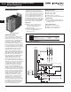
Figure 2.2-11. KYZ Input Module
Note: The Power Xpert Gateway 400/600
does not support KYZ pulses from the
DIM unit.
Frequency Range
■ 50/60 Hz
Power
■ 85 to 138 Vac (120 Vac nominal)
50/60 Hz; 100 mA.
■ 48 – 128 Vdc (48 Vdc nominal);
100 mA.
■ Brownout operation at 50% and 80%
of nominal ac and dc ratings.
■ Power input is provided from a
limited source, isolated from the
mains by double isolation.
■ Power for all inputs is supplied
from an internal, isolated 24 Vdc
power source.
Table 2.2-11. Specifications
Mounting Information
The DIM module is designed to be
DIN rail mountable. DIN rail must
be 1/3 inches H X 1-3/8 inches W
(8.5 mm H x 34.9 mm W).
Communications
The DIM is a fully compatible Power
Management Software communicating
device with built-in INCOM commu-
nications. The DIM comes complete
with a 3-pin connector to receive the
shielded twisted pair conductor.
All wiring must be complete as per
Instruction Leaflet TD17513, Wiring
Specification Base Rules.
Table 2.2-12. Ordering Information
Description Rating
Operating Temperature -20ºC to 60ºC
Storage Temperature -20ºC to 70ºC
Operating Humidity 5 to 90% Maximum
Noncondensing
Altitude 10,000 ft. (3,048 m)
Environment Indoor Use Only
Transient Overvoltage Category 2
Pollution 1º
Equipment Class 1
Catalog Number Description
DIM Digital Input Module