
System information


2.3-2
For more information visit: www.eaton.com CA08104001E
February 2009
Power Management Systems & Products
i
ii
1
2
3
4
5
6
7
8
9
10
11
12
13
14
15
16
17
18
19
20
21
Sheet 02
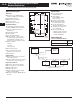
Power Xpert Systems and Network System Expansion
Application Information
030
Copper Ethernet Cable
Wiring Guidelines
The following information can be used
as a guide when designing an Ethernet
system using Copper Ethernet Cable.
■ Cables should not be routed near
equipment that generates strong
electric or magnetic fields such as
motors, drive controllers, arc weld-
ers and conduit.
■ Ethernet cable insulation has a volt-
age rating of 300 Vac. Use of barri-
ers, cable trays or high voltage
sheathing with STP Ethernet cable
may be required in installations with
cables carrying voltages greater
than 300 Vac. This may also be nec-
essary in order to comply with UL
requirements. In installations where
the cable cannot be physically sepa-
rated from the power cables (where
a physical barrier is not practical)
fiber optic cable should be used.
■ When crossing power conductors
with Ethernet cable, cross at right
angles.
■ Shielded Twisted Pair (STP) Ethernet
cable should be specified for use in
high noise environments. Shielded
shrouded connectors must be used
and the shield must be connected at
both ends of the wire. The mating
plug must have a shielded shroud
that is terminated to ground at both
ends. Where there is a possibility of
a difference in ground potential
(common mode) voltages between
the two terminated ends, fiber optic
cable is recommended.
■ When using conduit or a metal cable
tray, each section of the conduit or
tray must be bonded to each adja-
cent section and the conduit or tray
needs to be bonded to earth ground.
Do not allow the shields to touch the
conduit or metal tray at any point.
■ Only shielded (STP) Ethernet cables
should be placed into metal conduit.
Some UTP cables may not function
properly when installed in conduit,
as the metal conduit can affect
the electrical properties of an
unshielded cable. Consult the cable
manufacturer when installing UTP
cables in conduit.
■ As a general rule for noise protec-
tion, Ethernet Cable should maintain
a minimum distance of 3 inches
(8 cm) from electric power conduc-
tors for up to 100 volts and 1 inch
(3 cm) for each additional 100 volts
up to 400 volts. STP cable is
recommended.
■ For Ethernet cable run within
conduit but near conductors with
potentially noisy power conductors
carrying currents of greater than
20 A or voltages greater than 400 V,
maintain the following distances.
STP cable is required.
❑ Conductors of less than
20 A = 3 inches
❑ Conductors of 20 A or more
and up to 100 kVA = 6 inches
❑ Conductors greater than
100 kVA = 12 inches
■ For Ethernet cable run near
conductors with potentially noisy
power conductors carrying currents
of greater than 20 A or voltages
greater than 400 V, maintain the
following distances. STP cable is
recommended.
❑ Conductors of less than
20 A = 6 inches
❑ Conductors of 20 A or more
and up to 100 kVA = 12 inches
❑ Conductors greater than
100 kVA = 24 inches
■ Route Ethernet cable at least 5 feet
(1.5 m) from sources of rf/microwave
radiation. STP cable is required.
■ Do not cascade more than 4 Ethernet
repeaters (router, switch or hub)
within a network segment.
■ Environmentally sealed connectors
should be specified for cables used
in outdoor installations.
■ Avoid pinching the cable when using
cable ties.
■ Total distance between an Ethernet
Transmitter and Receiver at the end
points of the network should not
exceed 328 feet (100 m).
■ Total distance from a patch panel to
a wall jack (using solid cable) shall
not exceed 295 feet (90 m). Splices
are not permitted.
■ Patch cords used as cross-connect
jumpers in a patch panel should not
exceed 20 feet (6 m).
■ Patch cords from a wall jack to the
work area PC (or device) shall not
exceed 16 feet (5 m).
■ Ethernet cable used in harsh
environments must be selected to
withstand the following conditions:
vibration, air born contaminants,
chemicals, temperature, electro-
magnetic interference, combustible
atmospheres and local regulatory
standards such as UL and NEMA.
■ Ethernet connectors used in harsh
environments must be robust
enough to withstand vibration,
multiple connection cycles, tempera-
ture changes, and provide a proper
seal to protect against moisture,
dust/dirt and chemical attack.
■ Different cable media support differ-
ent bandwidth capabilities. When
installing cable in a network, care
should be taken to install the cable
that will fill current network loading
requirements and future expansion
needs. In general, fiber optic cable
can support the greatest bandwidth
(upwards of 25,000 gigabits) and
UTP has the lowest. CAT5e cabling is
designed to operate a bit rates up to
1000 Mb and CAT6 cable up to 2000
Mb.
■ Operating your cable at maximum
speed reduces the distance between
network segments. Check with your
cable supplier for specifications
regarding segment distance vs.
speed.
■ Cable with 5% impedance mismatch
or return loss of 27 to 32 dB is rec-
ommended. Ethernet cable imped-
ance can vary by as much as 15%
(85 to 115 Ohms). Average Ethernet
cable with 15% impedance variation
can have up to 10 dB additional
return loss. This discontinuity is
referred to as return loss, since it
causes some of the signal to be
reflected back down the cable
instead of propagating forward. It
is measured in decibels or ratio of
transmitted versus reflected signal.
Fiber Optic Technology
The use of fiber optics in telecommu-
nications and wide area networking
has been common for many years,
but more recently fiber optics have
become increasingly prevalent in
industrial data communications sys-
tems as well. High data rate capabili-
ties, noise rejection and electrical
isolation are just a few of the impor-
tant characteristics that make fiber
optic technology ideal for use in
industrial and commercial systems.
Although often used for point-to-point
connections, fiber optic links are being
used to extend the distance limitations
of RS-232, RS-422/485 and Ethernet
systems while ensuring high data
rates and minimizing electrical
interference.