Powerware® 9155 UPS-Mounted Bypass Switch User's Guide For use with Powerware 9155 8–15 kVA UPS Models
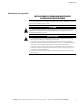
Class A EMC Statements FCC Part 15 NOTE This equipment has been tested and found to comply with the limits for a Class A digital device, pursuant to part 15 of the FCC Rules. These limits are designed to provide reasonable protection against harmful interference when the equipment is operated in a commercial environment.
Requesting a Declaration of Conformity Units that are labeled with a CE mark comply with the following harmonized standards and EU directives: S Harmonized Standards: IEC 62040-1-1 and IEC 62040-2; IEC 60950 Third Edition S EU Directives: 73/23/EEC, Council Directive on equipment designed for use within certain voltage limits 93/68/EEC, Amending Directive 73/23/EEC 89/336/EEC, Council Directive relating to electromagnetic compatibility 92/31/EEC, Amending Directive 89/336/EEC relating to EMC The EC Dec
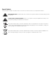
Special Symbols The following are examples of symbols used on the UPS or accessories to alert you to important information: RISK OF ELECTRIC SHOCK - Indicates that a risk of electric shock is present and the associated warning should be observed. CAUTION: REFER TO OPERATOR'S MANUAL - Refer to your operator's manual for additional information, such as important operating and maintenance instructions. This symbol indicates that you should not discard the UPS or the UPS batteries in the trash.
Table of Contents 1 2 3 Introduction . . . . . . . . . . . . . . . . . . . . . . . . . . . . . . . . . . . . . . . . . . . . . . . . . . . . . . . . 9 Safety Warnings . . . . . . . . . . . . . . . . . . . . . . . . . . . . . . . . . . . . . . . . . . . . . . . . . . . . . . . . . . . . . . . . . . . . 9 UPS-Mounted Bypass Switch Installation . . . . . . . . . . . . . . . . . . . . . . . . . . . . . . . . 13 MBM/PDM Setup . . . . . . . . . . . . . . . . . . . . . . . . . . . . . . . . . . . . . . .
TABLE OF CONTENTS ii EATON Powerware® 9155 UPS-Mounted Bypass Switch (8–15 kVA) User's Guide S 164201644 Rev A www.eaton.
Chapter 1 Introduction The Maintenance Bypass Module (MBM) and Power Distribution Module (PDM) are designed to work with an 8–15 kVA Powerware® 9155 uninterruptible power system (UPS). Both modules provide a Make-Before-Break (MBB) wrap-around bypass for UPS maintenance or service without shutting down the load. The PDM also comes equipped with several different types of output receptacles.
INTRODUCTION Consignes de Sécurité CONSIGNES DE SÉCURITÉ IMPORTANTES CONSERVER CES INSTRUCTIONS Ce manuel comporte des instructions importantes que vous êtes invité à suivre lors de toute procédure d'installation et de maintenance des batteries et de l'onduleur. Veuillez consulter entièrement ces instructions avant de faire fonctionner l'équipement et conserver ce manuel afin de pouvoir vous y reporter ultérieurement. DANGER! Cet onduleur contient des TENSIONS MORTELLES.
INTRODUCTION Advertencias de Seguridad INSTRUCCIONES DE SEGURIDAD IMPORTANTES GUARDE ESTAS INSTRUCCIONES Este manual contiene instrucciones importantes que debe seguir durante la instalación y el mantenimiento del SIE y de las baterías. Por favor, lea todas las instrucciones antes de poner en funcionamiento el equipo y guarde este manual para referencia en el futuro. PELIGRO Este SIE contiene VOLTAJES MORTALES.
INTRODUCTION 4 EATON Powerware® 9155 UPS-Mounted Bypass Switch (8–15 kVA) User's Guide S 164201644 Rev A www.eaton.
Chapter 2 UPS-Mounted Bypass Switch Installation This chapter describes the Maintenance Bypass Module (MBM) and Power Distribution Module (PDM) installation. Both modules have a Make-Before-Break (MBB) maintenance bypass switch. NOTE If you are installing an optional isolation transformer with the MBM, refer to the Powerware 9155 UPS (8–15 kVA) User's Guide for installation instructions. MBM/PDM Setup If you purchased an optional MBM/PDM, attach the module to the UPS before any wiring installation.
UPS-MOUNTED BYPASS SWITCH INSTALLATION 3. Attach the supplied L-bracket to the lower rear (for 2-high) or middle rear (for 3-high) cabinet using three screws (see Figure 2). Repeat for the other side. 4. Remove the UPS wiring access cover and retain. UPS Wiring Access Cover L-Bracket and Screws Figure 2. Attaching the L-Brackets 5. Remove the MBM/PDM wiring access cover and one of the conduit landing plates and retain. 6.
UPS-MOUNTED BYPASS SWITCH INSTALLATION 7. Secure the sides of the module to the L-brackets using six screws (see Figure 4). 8. Secure the top of the module to the top cabinet using four of the screws removed in Step 1. 9. Continue to the following section, “Wiring the MBM/PDM.” Screws for Top of Module Screws to L-Bracket (three each side) Figure 4. Securing the MBM or PDM (MBM Shown) EATON Powerware® 9155 UPS-Mounted Bypass Switch (8–15 kVA) User's Guide S 164201644 Rev A www.eaton.
UPS-MOUNTED BYPASS SWITCH INSTALLATION Wiring the MBM/PDM The Powerware 9155 UPS has the following power connections: S 2‐phase (L1 and L2), neutral, and ground connection for rectifier/bypass input S 2‐phase (L1 and L2), neutral, and ground connection for load output The nominal input/output voltages are: S 100/200, 110/220, or 120/240 Vac with 180° phase displacement S 120/208 or 127/220 Vac with 120° phase displacement Output overcurrent protection and disconnect switch must be provided by others.
UPS-MOUNTED BYPASS SWITCH INSTALLATION ON OFF Battery Circuit Breaker Figure 5. UPS with MBM Rear View 6. Punch two holes in the MBM/PDM conduit landing plate for the input and output conduit using a Greenlee® punch or similar device. 7. Hardwire the input, output, and ground terminations for the MBM/PDM. See Table 1 for specifications and Figure 6 for a detailed view of the MBM/PDM terminal block. TB10 Figure 6.
UPS-MOUNTED BYPASS SWITCH INSTALLATION NOTE Input neutral must be wired for proper operation. Failure to connect an input neutral will void the warranty. However, when wired with the optional isolation transformer, input neutral is supplied by the isolation transformer. Table 1. MBM/PDM Terminal Block (TB10) Wiring Input Circuit Breaker Rating Wire Function Input Ground L1 Neutral L2 Output Minimum Wire Size* Tightening Torque Conduit Connection (Entry Size) 120 lb in (13.
UPS-MOUNTED BYPASS SWITCH INSTALLATION 9. Replace the wiring access cover on the UPS. 10. Replace the MBM/PDM wiring access cover and conduit landing plate. 11. Continue to “Stabilizing the Cabinet” in the Powerware 9155 UPS (8–15 kVA) User's Guide to complete the installation. EATON Powerware® 9155 UPS-Mounted Bypass Switch (8–15 kVA) User's Guide S 164201644 Rev A www.eaton.
UPS-MOUNTED BYPASS SWITCH INSTALLATION Figure 8. UPS with MBM Wiring Diagram 12 EATON Powerware® 9155 UPS-Mounted Bypass Switch (8–15 kVA) User's Guide S 164201644 Rev A www.eaton.
UPS-MOUNTED BYPASS SWITCH INSTALLATION Figure 9. UPS with PDM Wiring Diagram EATON Powerware® 9155 UPS-Mounted Bypass Switch (8–15 kVA) User's Guide S 164201644 Rev A www.eaton.
UPS-MOUNTED BYPASS SWITCH INSTALLATION 14 EATON Powerware® 9155 UPS-Mounted Bypass Switch (8–15 kVA) User's Guide S 164201644 Rev A www.eaton.
Chapter 3 Maintenance Bypass Switch Operation This chapter describes: S Startup in Maintenance Bypass mode S Transferring the load to maintenance bypass S Returning the load to Normal mode The UPS-mounted maintenance bypass switch is part of the Maintenance Bypass Module (MBM) or Power Distribution Module (PDM) and is located on the back of the UPS (see Figure 10). Figure 10. Maintenance Bypass Switch (PDM Shown) The UPS-mounted bypass switch has three positions as described in Table 2.
MAINTENANCE BYPASS SWITCH OPERATION UPS-Mounted Bypass Switch Bypass User-Supplied Service Building Service Panel UPS Load Distribution Panel Bypass Service UPS Bypass Service UPS UPS EBM Figure 11. Typical Hardwired Installation with UPS-Mounted Bypass Switch Maintenance Bypass Startup To start the UPS in maintenance bypass: 1. Verify that the maintenance bypass switch is in the BYPASS position (see Figure 10). 2. Switch on utility power where the UPS is connected.
MAINTENANCE BYPASS SWITCH OPERATION Transferring the Load to Maintenance Bypass To transfer the load from the UPS to maintenance bypass: 1. Turn the maintenance bypass switch through the SERVICE position to the BYPASS position. The UPS battery circuit breaker trips, and the UPS is now bypassed, with the load powered by utility power. 2. The UPS automatically shuts down. Returning the Load to Normal Mode To transfer the load from maintenance bypass to the UPS: 1.
*164201644A* 164201644 A