
Instruction manual


COMMUNICATION
Eaton 9355 UPS (20/30 kVA) Installation and Operation Manual S 164201626 Rev C www.eaton.com/powerquality
63
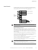
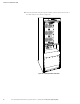
Control Terminals
The cables should be connected to the control terminals with a mating connector.
Input and output terminals have a functional isolation from terminal to terminal. They
are connected to the UPS chassis through individual 1 MΩ resistors.
+ Polarity
– Polarity
2
1
+ Polarity
– Polarity
2
1
2
1
2
1
Signal Input 1 (programmable)
Signal Input 2 (programmable)
REPO Normally Open
REPO Normally Closed
Normally Open
Normally Closed
1
2
Common
3
Relay Output
UPS
Connectors
(see Figure 36 on
page 53)
Figure 46. External Control Terminal Connections
NOTE If using a semiconductor switch type, pay attention to the proper polarity. A relay or other
mechanical control is preferred.
Remote Emergency Power-off
REPO is used to shut down the UPS from a distance. This feature can be used for
shutting down the load and the UPS by thermal relay, for instance in the event of
room overtemperature. When REPO is activated, the UPS shuts down all converters,
de-energizes all system relays, trips the battery circuit breaker, and fully powers down
within 1–2 minutes.
There are two REPO positions that may be used, normally-open or normally-closed.
The pins on the normally-closed REPO connector are connected together. When this
connection is open, the logic circuitry completely shuts down the UPS, thus
preventing the power from supplying the load.
If the use of normally-closed REPO operation is desired, replace the connector with a
normally-closed external switch (see Figure 36 on page 53).
If the use of normally-open REPO operation is desired, connect a normally-open
external switch (see Figure 36 on page 53).
NOTE To restart the UPS, reconnect the REPO connector pins and turn on the UPS manually. The pins must
be shorted to keep the UPS running. Maximum resistance is 10 ohm.
NOTE Leave the REPO connector installed in the REPO port on the UPS even if the REPO function is not
needed.